Supercharge Your Innovation With Domain-Expert AI Agents!

Chuck

A chuck and disc body technology, applied in the direction of chucks, etc., can solve the problems of low production efficiency, achieve the effects of improving production efficiency, making changes small and easy to implement, and reducing production costs

Active Publication Date: 2022-04-12
浙江海德曼智能装备股份有限公司
View PDF11 Cites 0 Cited by
  • Summary
  • Abstract
  • Description
  • Claims
  • Application Information

AI Technical Summary

Problems solved by technology

[0004] The purpose of the present invention is to solve the above-mentioned problems in the prior art, and propose a chuck to solve the problem of low production efficiency

Method used


Image

  • Chuck
  • Chuck
  • Chuck

Examples


Embodiment Construction

[0034] The following are specific embodiments of the present invention and in conjunction with the accompanying drawings, the technical solutions of the present invention are further described, but the present invention is not limited to these embodiments.

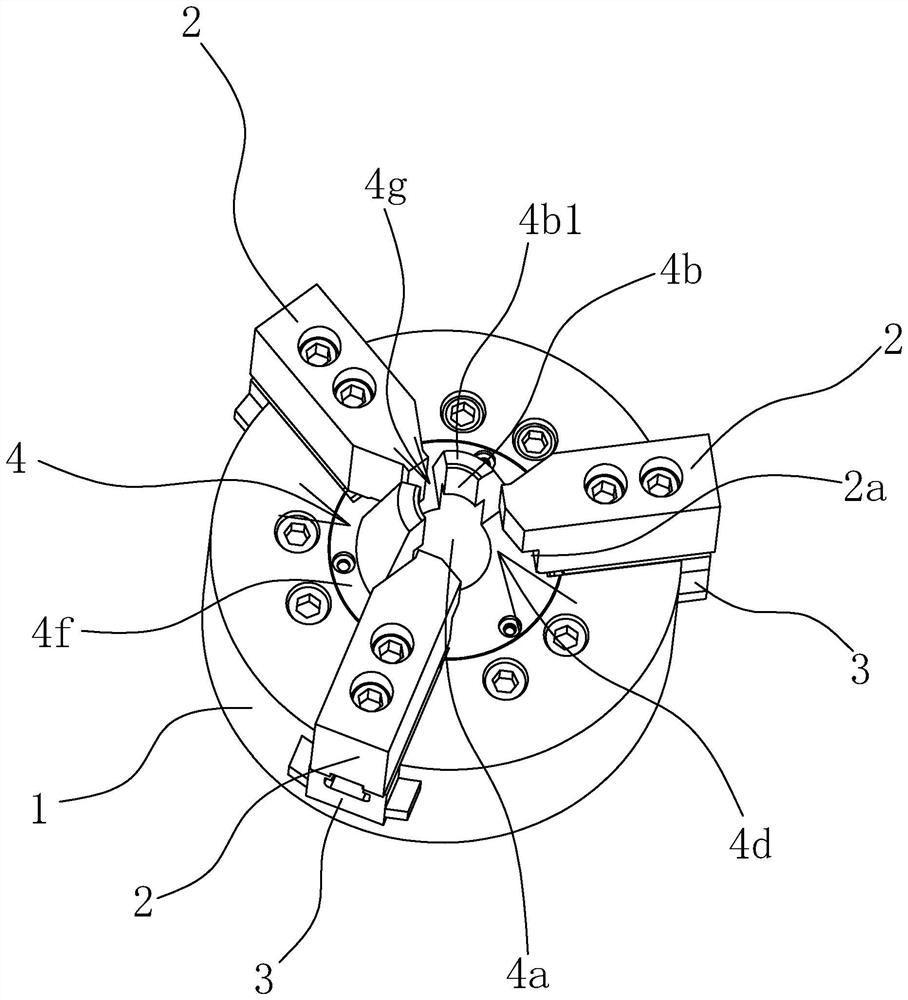
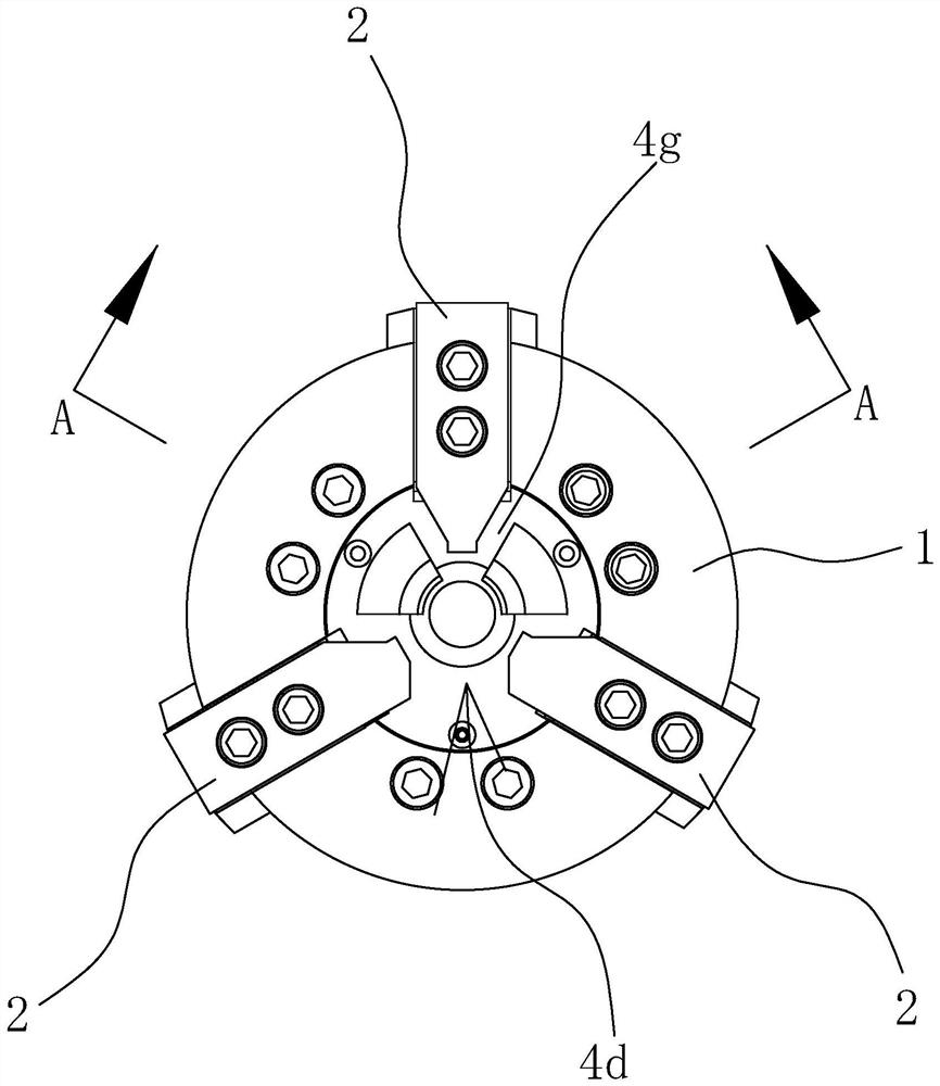
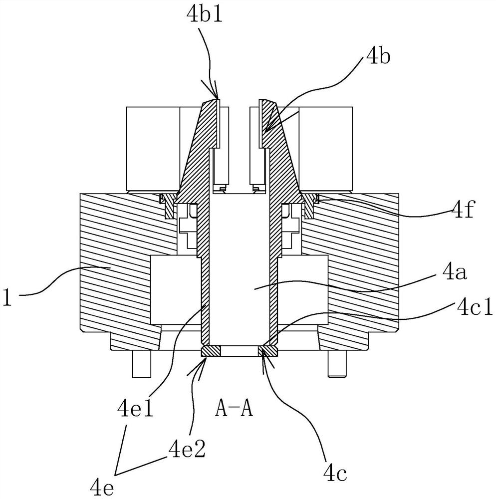
[0035] Such as figure 1 , figure 2 , image 3 , Figure 4 , Figure 5 and Figure 6As shown, a chuck includes a disc body 1 and several claws 2 distributed in the front end of the disc body 1 along the circumferential direction and capable of moving along the radial direction of the disc body 1 at the same time. Specifically, the front end of the disc body 1 is slidingly connected with A plurality of slide blocks 3, each claw 2 is fixed on the slide block 3. The front end of the disc body 1 is fixed with a positioning piece 4, and the positioning piece 4 is provided with a positioning hole 4a along the front and rear direction. The front side of the shoulder 4b has a positioning plane 1 4b1, and the front side of th...


PUM


Abstract

The invention provides a chuck, and belongs to the technical field of clamps. The problem of low production efficiency is solved. The chuck comprises a chuck body and a plurality of clamping jaws distributed at the front end of the chuck body in the circumferential direction, a positioning piece is fixed to the front end of the chuck body, a positioning hole is formed in the positioning piece in the front-back direction, a first positioning protruding shoulder is arranged at a front-end hole opening of the positioning hole, a second positioning protruding shoulder is arranged at a rear-end hole opening of the positioning hole, and a feeding opening allowing a workpiece to be placed into the positioning hole is formed in the side portion of the front end of the positioning piece. The front end of the positioning piece is higher than the clamping jaws, and the clamping jaws can stretch into the front end of the positioning piece at the same time. The method has the advantages of high production efficiency, reduction of enterprise production cost, easiness in implementation and the like.

Description

technical field [0001] The invention belongs to the technical field of clamps and relates to a chuck. Background technique [0002] In the existing connection structure, flange bolts are often used. It is different from conventional bolts in that it has a flange in addition to a rod and a head, wherein the rod and the head are integrally connected to the flange. sides. In the processing of flange bolts, two processes are essential, one of which is turning the end face of the rod and machining the center hole, and the other is turning the outer circle of the rod. In the process of turning the end face of the rod and machining the center hole, the processing position is at the end of the rod. Because the length of the rod is relatively long, the clamping position is required to be as close as possible to the end of the rod. In order to avoid machining errors due to the fact that the clamping position is too far away from the end of the rod during processing; and in the proce...

Claims


Application Information

Patent Timeline
IPC IPC(8): B23B31/10
Inventor 程万里葛建伟高兆春张涛蒋利军
Owner 浙江海德曼智能装备股份有限公司
Features
  • R&D
  • Intellectual Property
  • Life Sciences
  • Materials
  • Tech Scout
  • Unparalleled Data Quality
  • Higher Quality Content
  • 60% Fewer Hallucinations
Learn More