
End effector for tunnel detection robot, detection robot and control method thereof

A technology of end effectors and robots, which is applied in the direction of program control manipulators, manipulators, manufacturing tools, etc., can solve problems such as harsh working environment, long tunnel distance, affecting detection stability and precision, etc., to improve safety and stability, Improve efficiency and precision, improve the effect of adjustment flexibility

Pending Publication Date: 2022-04-08
SHANDONG UNIV
View PDF0 Cites 0 Cited by
  • Summary
  • Abstract
  • Description
  • Claims
  • Application Information

AI Technical Summary

Problems solved by technology

[0002] At present, the construction cycle of the tunnel is very long, and the use and design cycle is very long. The long-term tunnel will be affected by geological and natural environmental reasons, and regular inspections are required to ensure the normal use of the tunnel; the current tunnel inspection process is Manual inspection requires qualified and experienced technicians to complete the operation. The distance of the tunnel is very long, the work of tunnel inspection is very heavy, the working environment is relatively harsh, the light in the tunnel is dark, and there are dust and toxic substances.
The ever-increasing tunnel construction has led to more arduous work, which has given birth to the automation process of tunnel inspection, so the tunnel inspection robot came into being
[0003] The inventors found that the current related tunnel detection equipment is installed on a manually driven vehicle or a climbing car, not a robot with automatic navigation and automatic driving, and has not realized the complete automation of tunnel detection; moreover, the end effector and When the inner wall of the tunnel is in contact with the test, it cannot achieve good self-adaptive adjustment and better fit, which affects the stability and accuracy of the test

Method used


Image

  • End effector for tunnel detection robot, detection robot and control method thereof
  • End effector for tunnel detection robot, detection robot and control method thereof
  • End effector for tunnel detection robot, detection robot and control method thereof

Examples


Embodiment 1

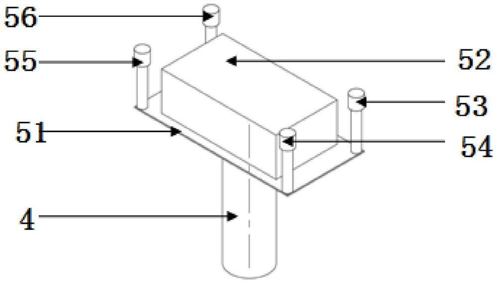
[0043] Such as figure 1 As shown, this embodiment provides an end effector for a tunnel detection robot, including an end effector frame 51, and an ultrasonic radar 52 arranged on the end effector frame 51;

[0044] A plurality of contact switches are arranged on the working surface of the end effector frame 51 .

[0045] In this embodiment, the end effector frame 51 is a rectangular frame, and the four corners of the rectangular frame are provided with contact switches; respectively the first contact switch 53, the second contact switch 54, and the third contact switch 54 and the fourth contact switch 55;

[0046] Specifically, a plurality of contact switches are provided on the working surface of the end effector frame 51, through the cooperation of the plurality of contact switches, the bonding between the end effector and the ultrasonic radar 52 and the detection object is realized. In this implementation, the detection object is The inner wall of the tunnel improves the...

Embodiment 2

[0048] This embodiment provides a method for controlling an end effector for a tunnel inspection robot, using the end effector for a tunnel inspection robot as described in Embodiment 1, including:

[0049] When only one contact switch touches the detection object, the coordinate system is established with the contact point, and the end effector frame 51 rotates around any side where the contact point meets;

[0050] When two adjacent contact switches touch the detection object, a coordinate system is established with the midpoint of the line connecting the two contact points, and the end effector frame 51 rotates around the line connecting the two contact points until three contact switches touch the detection object;

[0051] When two diagonal contact switches touch the detection object, a coordinate system is established with the center of the end effector frame, and the end effector frame 51 rotates around the diagonals of the two contact switches until three contact switches...

Embodiment 3

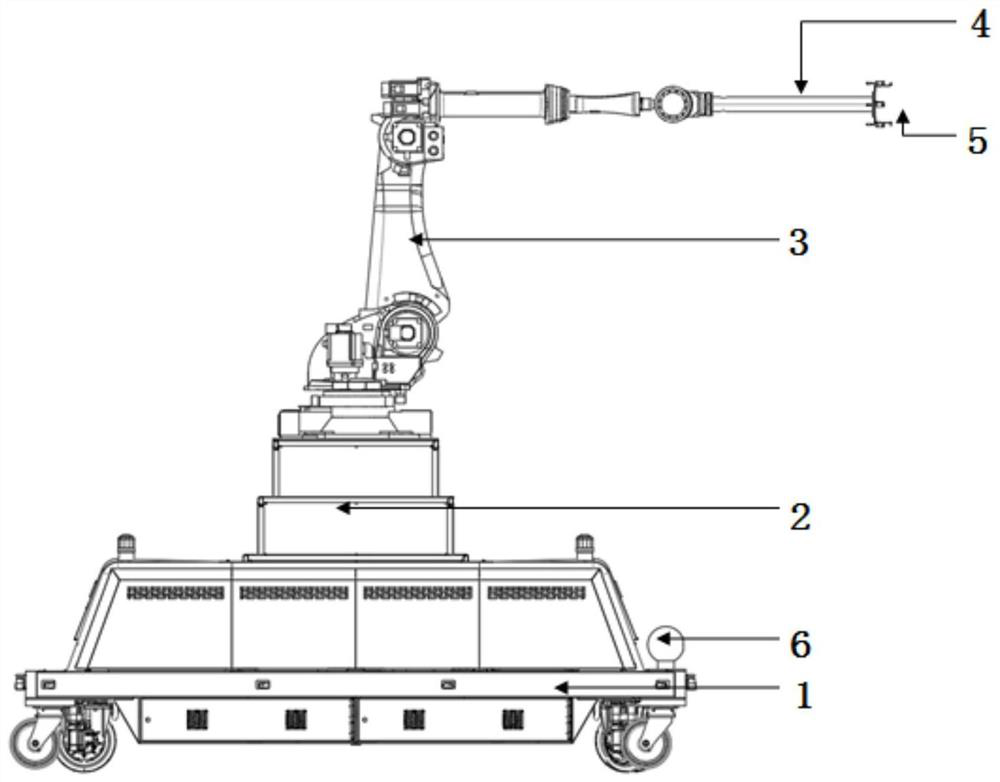
[0054] This embodiment provides a detection robot, including a robot mobile platform 1, a lift 2, a mechanical arm 3, an extension rod 4, an end effector 5, a laser radar 6 and a gyroscope; the mechanical arm 3 can be set as a six-axis mechanical Arm, the lidar 6 can be set as a 3D lidar.

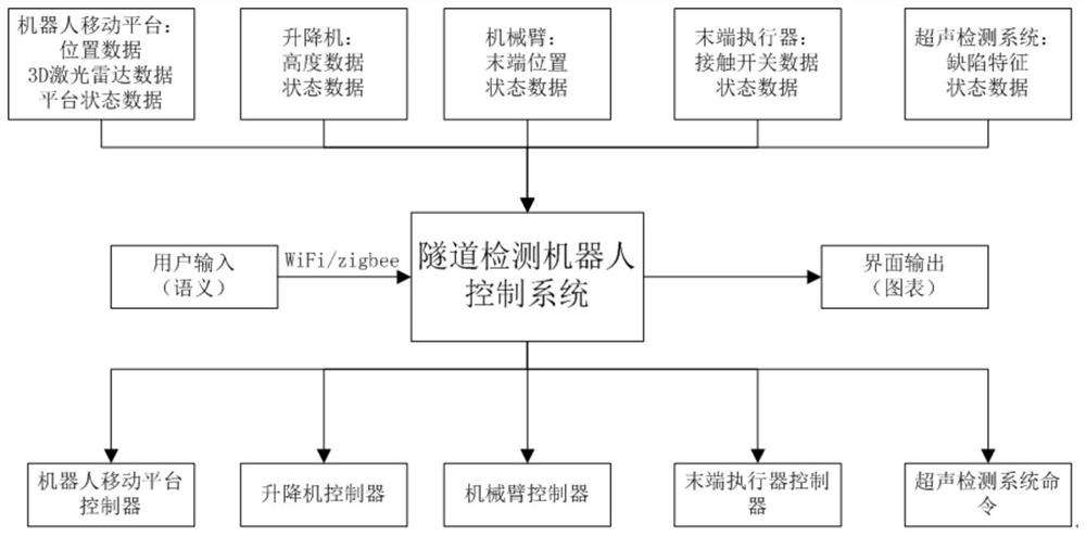
[0055] The robot mobile platform 1 is equipped with a 3D laser radar and a gyroscope, the elevator 2 is installed above the platform, a six-axis mechanical arm is installed above the elevator 2, and the extension rod 4 is installed at the end of the six-axis mechanical arm. The end effector 5 is installed at the end of the rod 4; the robot is equipped with a server as the control center of the robot, and the control center receives the input of the operator's tunnel detection, and realizes communication with the control systems of each part according to the control logic according to the input data of each part of the system. The control system of each part realizes automatic walking and de...


PUM


Abstract

The invention provides an end effector for a tunnel detection robot, the detection robot and a control method of the detection robot. The end effector comprises a robot moving platform, a lifting machine arranged on the robot moving platform and a mechanical arm arranged on the lifting machine. A lengthening rod is arranged at the end, away from the lifting machine, of the mechanical arm, and an end effector is arranged at the end, away from the mechanical arm, of the lengthening rod. The end effector comprises an end effector frame and an ultrasonic radar arranged on the end effector frame; a plurality of contact switches are arranged on the working surface of the end effector frame; according to the invention, a plurality of contact switches are arranged on the working surface of the frame of the end effector, and the fitting of the end effector and the ultrasonic radar with the inner wall of the tunnel is realized through the cooperation of the plurality of contact switches, so that the fitting efficiency and precision are improved, and the stability of detecting the inner wall of the tunnel by the ultrasonic radar is improved; and conditions are created for improving the detection accuracy.

Description

technical field [0001] The invention belongs to the technical field of tunnel detection robots, and in particular relates to an end effector for a tunnel detection robot, a detection robot and a control method thereof. Background technique [0002] At present, the construction cycle of the tunnel is very long, and the use and design cycle is very long. The long-term tunnel will be affected by geological and natural environmental reasons, and regular inspections are required to ensure the normal use of the tunnel; the current tunnel inspection process is Manual inspection requires qualified and experienced technicians to complete the operation. The distance of the tunnel is very long, the work of tunnel inspection is very heavy, the working environment is relatively harsh, the light in the tunnel is dark, and there are dust and toxic substances. The ever-increasing tunnel construction has led to more arduous work, which has given birth to the automation process of tunnel insp...

Claims


Application Information

Patent Timeline
Patent Type & Authority Applications(China)
IPC IPC(8): B25J11/00B25J9/16B25J13/08B25J18/02
Inventor 高新彪周军皇攀凌李留昭邓建新孙云伟
Owner SHANDONG UNIV
Learn More