
Calibration method, device and system for powder spreading device

A powder spreading device and powder spreading technology, which is applied in the direction of additive processing, etc., can solve the problems of strong subjectivity, inability to accurately judge the size of the pressing force of the feeler gauge, and abnormal shape of the molded parts.

Pending Publication Date: 2022-04-08
HUNAN FARSOON HIGH TECH CO LTD
View PDF11 Cites 0 Cited by
  • Summary
  • Abstract
  • Description
  • Claims
  • Application Information

AI Technical Summary

Problems solved by technology

[0003] During the powder spreading process, if the powder spreading device is in a tilted or deformed state, the height of the spread powder is different, resulting in abnormal shape of the molded part, and the accurate restoration of the scanned information cannot be realized. Therefore, the powder spreading device needs to be calibrated before the system runs
The traditional method uses a feeler gauge equidistant measurement tool to measure the gap height difference between the powder spreading scraper and the forming substrate for adjustment. During the measurement process, the extrusion force of the feeler gauge cannot be accurately judged, and it is highly subjective. error, resulting in poor calibration accuracy

Method used


Image

  • Calibration method, device and system for powder spreading device
  • Calibration method, device and system for powder spreading device
  • Calibration method, device and system for powder spreading device

Examples


Embodiment Construction

[0021]The technical solutions of the present application will be clearly and completely described below in conjunction with the embodiments. Apparently, the described embodiments are part of the embodiments of the present application, not all of them. Based on the embodiments in this application, all other embodiments obtained by persons of ordinary skill in the art without making creative efforts belong to the scope of protection of this application.

[0022] The calibration method of the traditional powder spreading device is to use a feeler gauge equidistant measuring tool to measure the gap height difference between the powder spreading scraper and the forming substrate for adjustment. During the measurement process, the extrusion force of the feeler gauge cannot be accurately judged, which is highly subjective. Various errors are easily introduced during operation, resulting in poor calibration accuracy.

[0023] Based on this, the embodiment of the present application pr...


PUM


Abstract

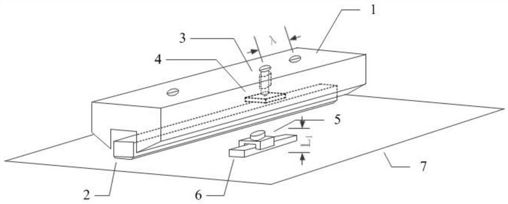
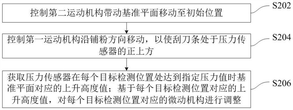
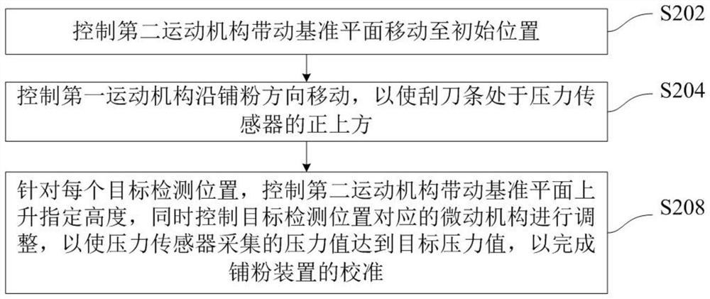
The invention provides a calibration method, device and system for a powder spreading device. The method is applied to a control system. The control system is connected with a first movement mechanism arranged in a powder spreading device in an equipment forming area, a micro-motion mechanism arranged in an adjusting hole of the first movement mechanism, a second movement mechanism arranged below the powder spreading device and corresponding to a reference plane, and a pressure sensor arranged on a guide rail on the reference plane. The powder spreading device further comprises a scraper strip embedded and fixed in the first movement mechanism; the first movement mechanism drives the scraper strip to do reciprocating motion in the equipment forming area in the powder laying direction; a plurality of adjusting holes are formed in the first movement mechanism; a micro-motion mechanism is arranged in each adjusting hole, and a movable pressing block is arranged below each micro-motion mechanism; the inching mechanism adjusts the embedding height of the scraper strip in the first movement mechanism by applying pressure to the movable pressing block. Calibration based on the structure can improve the calibration precision of the powder spreading device.

Description

technical field [0001] The present application relates to the technical field of fusion rapid prototyping, in particular to a method, device and system for calibrating a powder spreading device. Background technique [0002] The basic process of selective laser melting molding is: a heating device is installed under the area to be formed to preheat the forming base plate, and then the scanning system (galvanometer) controls the high-energy laser beam to act on the area to be formed according to the layered slice information of the three-dimensional model of the formed part. In the powder in the molding area, most of the energy is absorbed and converted into heat energy of the powder, so that the temperature of the powder rises rapidly to above the melting point and melts. After a layer is scanned, the piston in the forming cylinder will drop a layer thickness; the powder feeding device will send a certain amount of powder to the working table, and the powder spreading system...

Claims


Application Information

Patent Timeline
Patent Type & Authority Applications(China)
IPC IPC(8): B22F12/60B22F12/90B33Y30/00B33Y50/00
CPCY02P10/25
Inventor 姜源源彭伟刘鑫炎许小曙
Owner HUNAN FARSOON HIGH TECH CO LTD
Learn More