
Frame capture synchronization method and device

A frame boundary and peak position technology, applied in the field of frame capture synchronization methods and devices, can solve problems such as large noise interference and poor synchronization performance, and achieve the effects of high synchronization performance, strong frequency offset resistance, and improved synchronization performance.

Pending Publication Date: 2022-04-01
SPL ELECTRONICS TECH CO LTD
View PDF7 Cites 2 Cited by
  • Summary
  • Abstract
  • Description
  • Claims
  • Application Information

AI Technical Summary

Problems solved by technology

[0005] The present invention provides a frame capture synchronization method and device, which are used to solve the problem of poor synchronization performance in the synchronization method in the prior art when the noise interference is relatively large and the signal-to-noise ratio is low

Method used


Image

  • Frame capture synchronization method and device
  • Frame capture synchronization method and device
  • Frame capture synchronization method and device

Examples


Embodiment Construction

[0031] In order to make the object, technical solution and technical effect of the present invention clearer, the present invention will be further described in detail below in conjunction with the accompanying drawings and specific embodiments.

[0032] Embodiment of frame capture synchronization method:

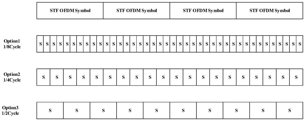
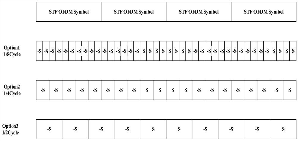
[0033] figure 1 is the physical signal frame structure diagram, figure 2 is the STF base layer frame format, image 3 is the STF frame format, Figure 4 is a schematic flowchart of the frame capture synchronization method of the present invention. The specific flow of the frame capture synchronization method of this embodiment is as follows:

[0034] Step 1: Obtain the received signal and its first power value, and calculate the cross-correlation value between the received signal and the local short training domain sequence.

[0035] In step 1, the received signal is a baseband sampled time-domain signal. Baseband sampling time domain signal using figure 1 High Spee...


PUM


Abstract

The invention relates to a frame capture synchronization method and device, and the method comprises the steps: obtaining a received signal and a first power value thereof, calculating a cross-correlation value between the received signal and a local short training domain sequence, and obtaining a frame boundary position according to the cross-correlation value and the first power value, the short training domain sequence of the received signal comprising a scrambling code layer; calculating a time domain self-correlation value and a second power value of the received signal from the frame boundary position; peak value judgment is carried out in a second preset search window according to the time domain self-correlation value and the second power value, peak value search is carried out on the received signals meeting the peak value judgment condition in the second preset search window, the maximum judgment value in peak value judgment is found out, and the judgment value is the ratio of the time domain self-correlation value to the second power value; the position corresponding to the maximum value is a synchronization point position, so that synchronization success is judged. According to the invention, the problem of poor synchronization performance of a synchronization method in the prior art under the conditions of large noise interference and low signal-to-noise ratio can be solved.

Description

technical field [0001] The invention belongs to the technical field of OFDM communication, and in particular relates to a frame capture synchronization method and device. Background technique [0002] Orthogonal Frequency-Division Multiplex (OFDM) has been widely used in many high bit rate communication systems. Since OFDM systems are very sensitive to synchronization errors, precise timing synchronization will greatly affect system performance, and a reliable synchronization scheme must be designed for OFDM systems. [0003] The synchronization research of OFDM system has a long history, and many synchronization methods have been proposed. Among various timing synchronization algorithms based on training sequences, sliding autocorrelation is the most commonly used method. This method obtains the starting point of the frame by finding the peak point of the sliding autocorrelation of the leading sequence with a well-designed structure. The most representative one is the Sc...

Claims


Application Information

Patent Timeline
Patent Type & Authority Applications(China)
IPC IPC(8): H04L27/26
CPCY02D30/70
Inventor 黄梅莹吴义文孙胤杰陈飞飞楼红伟李正卫
Owner SPL ELECTRONICS TECH CO LTD
Learn More