A street lamp lighting control method and system for moving object detection

A technology for moving objects and lighting control, applied in energy-saving control technology, image analysis, instruments, etc., can solve the problems that cannot be controlled according to the actual application requirements, and the lighting control method depends on the external environment control, so as to improve the utilization rate and lighting effect. , Conducive to the effect of energy saving control

Active Publication Date: 2022-05-24
深圳市帝景光电科技有限公司
View PDF7 Cites 0 Cited by
  • Summary
  • Abstract
  • Description
  • Claims
  • Application Information

AI Technical Summary

Problems solved by technology

[0004] In order to solve the problem that the current lighting control method relies too much on the control of the external environment and cannot be controlled according to actual application requirements, the present invention provides a street lighting control method and system for moving object detection, which performs targeted lighting control by means of image analysis on the lighting scene. Provide lighting, enable the lighting facilities, adjust the brightness and switch the corresponding operation mode without human contact operation, greatly improve the user experience, improve the utilization rate and lighting effect of lighting facilities such as street lights

Method used


Image

  • A street lamp lighting control method and system for moving object detection
  • A street lamp lighting control method and system for moving object detection
  • A street lamp lighting control method and system for moving object detection

Examples


Embodiment Construction

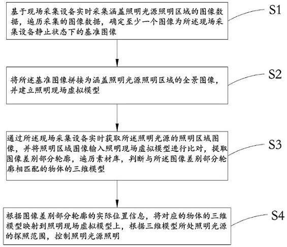
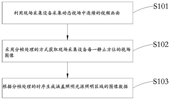
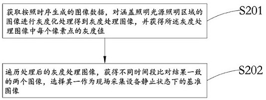
[0049] In order to make the objectives, technical solutions and advantages of the present invention clearer, the present invention will be further described in detail below with reference to the accompanying drawings and embodiments. It should be understood that the specific embodiments described herein are only used to explain the present invention, but not to limit the present invention.

[0050] In some of the processes described in the description and claims of the present invention and the above-mentioned drawings, various operations are included in a specific order, but it should be clearly understood that these operations may not be in accordance with the order in which they appear herein. For execution or parallel execution, the sequence numbers of the operations, such as 101, 102, etc., are only used to distinguish different operations, and the sequence numbers themselves do not represent any execution order. Additionally, these flows may include more or fewer operati...


PUM


Abstract

The invention relates to the technical field of traffic control regulation, in particular to a street lamp lighting control method and system for moving object detection. The method is to collect image data covering the illumination area of ​​the illumination source in real time based on the on-site acquisition equipment; determine at least one image as a reference image in a static state of the on-site acquisition equipment; splice the reference image into a panoramic image covering the illumination area of ​​the illumination source, and establish the lighting On-site virtual model; through the on-site acquisition equipment to obtain the lighting area image of the lighting source in real time, input the lighting scene virtual model for comparison, and extract the outline of the difference in the image; traverse the material library, determine the 3D model of the object that matches the outline of the difference in the image, and According to the actual position information of the outline of the difference part of the image, the 3D model of the corresponding object is mapped to the virtual model of the lighting scene, and the lighting of the lighting source is controlled according to the search range of the lighting source where the 3D model is located.

Description

technical field [0001] The present invention relates to the technical field of traffic control and regulation, in particular to a street lamp lighting control method and system for detecting moving objects. Background technique [0002] With the development of social economy and the continuous improvement of urban infrastructure construction, lighting system is a necessary public facility in urban construction, and the effective control of lighting system is an important link related to the vital interests of citizens. At present, the control and management of street lamps on urban roads are convenient, and the rational control of lighting systems can save energy and improve the utilization rate and lighting effects of lighting facilities such as street lamps. Therefore, the control of the lighting system has become an urgent problem to be solved. [0003] The current lighting control usually uses the light intensity signal to automatically control the lighting of the lamps...

Claims


Application Information

Patent Timeline
Patent Type & Authority Patents(China)
IPC IPC(8): G06T7/00
CPCY02B20/40
Inventor 钟则隆钟则林
Owner 深圳市帝景光电科技有限公司
Why Eureka
Try Eureka