Zone area light storage and charging cloud side collaboration method and system

A technology of optical storage and platform area, applied in system integration technology, information technology support system, photovoltaic power generation, etc., can solve the problems of inconspicuous control effect, control oscillation, miscontrol, etc., and achieve optimal utilization, high real-time performance, and connection wide range of effects

Active Publication Date: 2022-03-25
南京瀚元科技有限公司
View PDF3 Cites 3 Cited by
  • Summary
  • Abstract
  • Description
  • Claims
  • Application Information

AI Technical Summary

Problems solved by technology

However, in practical applications, customers do not know how much data can be set to optimize the control strategy of the gateway, so customers often do not set parameters, and the gateway has been running at the factory default value
The default parameters of the gateway are not combined with the specific actual situation of the station area. The load type and control mode are all based on default experience. When controlling reactive power and voltage (power quality), there is a high probability of miscontrol, control oscillation, and poor control effect. Obvious, even counterproductive, control issues

Method used


Image

  • Zone area light storage and charging cloud side collaboration method and system
  • Zone area light storage and charging cloud side collaboration method and system
  • Zone area light storage and charging cloud side collaboration method and system

Examples


Embodiment 1

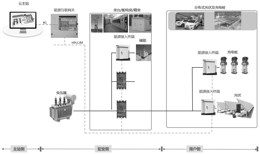
[0040] Referring to 1 to 2, it is an embodiment of the present invention, which provides a coordination method for optical storage, cloud and edge in the platform area, including:

[0041] S1: Use the energy access terminal 100 to obtain real-time operation data.

[0042] It should be noted that real-time operation data includes real-time operation data of photovoltaic, energy storage, and charging pile equipment;

[0043] Photovoltaic data include: grid-connected point current, grid-connected point voltage, power generation, and grid-connected point power factor;

[0044] Energy storage data include: grid-connected point current, grid-connected point voltage, active power, reactive power, energy storage battery SOC, operating mode;

[0045] The charging pile equipment data includes: charging pile charging power, current, voltage, charging pile charging mode, and accumulated charging power;

[0046] Operation data of station area: three-phase current, three-phase voltage, ac...

Embodiment 2

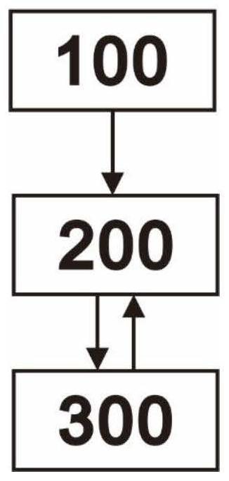
[0114] refer to image 3 This embodiment is another embodiment of the present invention. This embodiment is different from the first embodiment in that it provides a coordination system for optical storage, charging, cloud, and edge in the platform area. The above-mentioned coordination method for optical storage, filling, cloud, and edge in the area can be realized by relying on this system.

[0115] Specifically, the system includes:

[0116] The energy access terminal 100 is used to obtain real-time operation data;

[0117] The energy internet gateway 200 is connected to the energy access terminal 100, and is used to receive the real-time operation data acquired by the energy access terminal 100, process the abnormal data, and store the processed data locally;

[0118] The cloud master station 300 is connected with the energy internet gateway 200, and is used to obtain the data processed by the energy internet gateway 200, and perform voltage sensitivity analysis and calcu...


PUM


Abstract

The invention discloses a transformer area light storage and charging cloud side collaboration method and system, and the method comprises the steps: obtaining real-time operation data, processing abnormal data, and storing the data; performing voltage sensitivity analysis calculation on each node of the transformer area by combining the transformer area topological data; according to the calculation result, the correlation coefficient of the voltage offset of each node in the energy internet gateway and the injection power is updated in real time, and the abnormal correlation coefficient is identified and eliminated; the compensation tasks of the nodes near the downstream of the compensation nodes are jointly undertaken by the compensation nodes, and the compensation capacity of the compensation points giving consideration to the compensation effect of the downstream nodes is obtained; issuing the execution task, and returning and evaluating an execution result. The method can play advantages in the fields of long-term maintenance, business decision support and the like, can process and analyze the light storage and charging control in a real-time and short-period manner, realizes the light storage and charging control taking the electric energy quality and the photovoltaic absorption as core targets in the transformer area, optimizes the utilization of light storage and charging resources, and realizes the electric energy quality optimization of the transformer area, the efficient photovoltaic absorption and peak load shifting.

Description

technical field [0001] The present invention relates to the technical field of edge-cloud collaboration, and in particular to a method and system for cloud-edge collaboration of optical storage charging in a platform area. Background technique [0002] At present, a large number of distributed photovoltaics are connected to low-voltage station areas, and there are problems such as small capacity, large quantity, uneven distribution, and difficult management. In addition, distributed photovoltaics, energy storage, loads, charging piles or topological structures in the user-side power grid are different, so it is impossible to target The operating status of the low-voltage platform area is effectively coordinated and controlled. [0003] The existing coordinated control of optical storage and charging mainly considers local control in the station area, but limited by the computing and storage capabilities of the local terminal (fused terminal), the analysis dimension of local ...

Claims


Application Information

Patent Timeline
Patent Type & Authority Applications(China)
IPC IPC(8): H02J13/00H02J3/38H02J3/32H02J3/16H02J3/06
CPCH02J13/00004H02J13/00006H02J3/38H02J3/32H02J3/16H02J3/06H02J2300/24H02J2203/10Y02E10/56Y02E40/30Y02E40/70Y02E70/30Y02B90/20Y04S10/50Y04S10/52Y04S10/123Y04S20/12Y04S40/12
Inventor 吉彬韩超马超季桂荣陈尚卫
Owner 南京瀚元科技有限公司
Why Eureka
Try Eureka