
Switch cabinet connector safety monitoring system and control method

A safety monitoring and connector technology, which is applied to the parts, connections, electrical components of the connecting device, etc., can solve the problems of limited loop heating, no hierarchical safety defect analysis alarm, single alarm function, etc., to achieve small temperature measurement errors, Overcome limitations and hidden dangers and reduce the effect of wiring in the cabinet

Active Publication Date: 2022-03-25
DALIAN HUARUI HEAVY IND GRP CO LTD
View PDF6 Cites 0 Cited by
  • Summary
  • Abstract
  • Description
  • Claims
  • Application Information

AI Technical Summary

Benefits of technology

This technology allows for accurate monitoring of connections between different parts within an electric device's housing without affecting its overall design or performance. It uses special sensory devices called detective markers embedded throughout these materials to measure their temperatures and stresses during operation. These measurements help identify potential issues before they become serious enough. By combining this process with algorithms designed specifically for analyzing and determining work states, various alert systems may sound when there has been any problem with one part but cannot tell how bad another component was doing right now.

Problems solved by technology

This patents describes different ways to prevent damage caused during maintenance workings such as connecting cables between electronic devices (Electric Switches). However, this issue cannot be easily detected because existing techniques require manual inspections that may result in errors. Additionally, these conventional systems lack advanced fuzzy logic capabilities to analyze potential issues quickly without false alarms.

Method used


Image

  • Switch cabinet connector safety monitoring system and control method
  • Switch cabinet connector safety monitoring system and control method
  • Switch cabinet connector safety monitoring system and control method

Examples


Embodiment Construction

[0051] It should be noted that, in the case of no conflict, the embodiments of the present invention and the features in the embodiments can be combined with each other. The present invention will be described in detail below with reference to the drawings and in conjunction with the embodiments.

[0052] In order to make the purpose, technical solutions and advantages of the embodiments of the present invention clearer, the technical solutions in the embodiments of the present invention will be clearly and completely described below in conjunction with the drawings in the embodiments of the present invention. Obviously, the described embodiments It is only some embodiments of the present invention, but not all embodiments. The following description of at least one exemplary embodiment is merely illustrative in nature and in no way taken as limiting the invention, its application or uses. Based on the embodiments of the present invention, all other embodiments obtained by pers...


PUM


Abstract

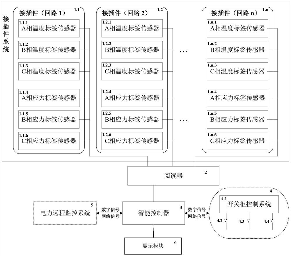
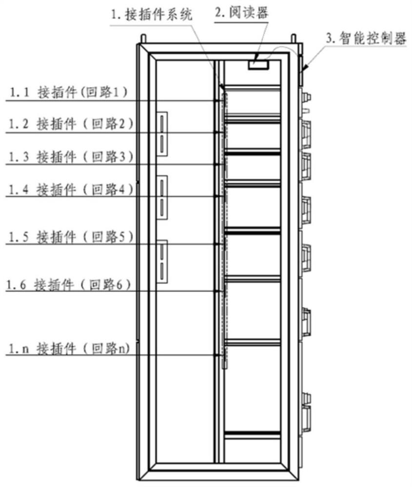
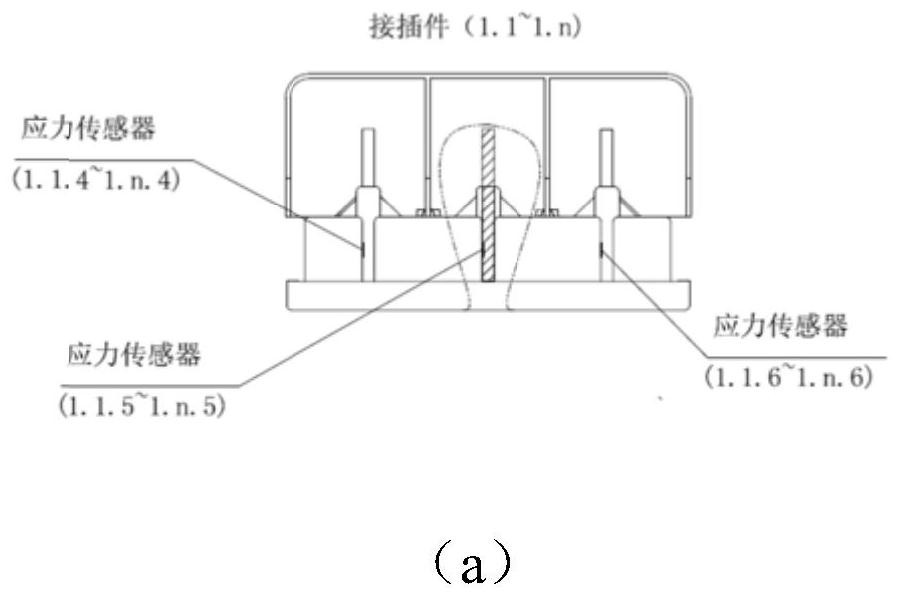
The invention relates to a switch cabinet connector safety monitoring system, which belongs to the technical field of electrical system engineering, n loop connectors for supplying power in a plug-in manner are arranged in a switch cabinet, and the system comprises n miniature temperature label sensors and n miniature stress label sensors, a reader; the intelligent controller is used for receiving the temperature signals and the contact stress signals of the n connectors transmitted by the reader, storing the temperature signals and the contact stress signals of the n connectors, respectively carrying out safety level fault judgment on the temperature signals and the contact stress signals of the n connectors, comparing safety fault levels, and sending the safety fault levels to the reader; outputting the highest-level safety fault signal of the connector with the fault; the working state of the connector can be accurately monitored in real time, and early warning, alarming and fault processing can be carried out. Even under the conditions of low current and no power transmission, the faults such as poor contact of the connector and no plugging in place can be judged.

Description


Claims


Application Information

Patent Timeline
Owner DALIAN HUARUI HEAVY IND GRP CO LTD
Learn More