A fully degaussing device for electronic communication equipment
A kind of communication equipment, technology of degaussing device
- Summary
- Abstract
- Description
- Claims
- Application Information
AI Technical Summary
Problems solved by technology
Method used
Image
Examples
Embodiment 1
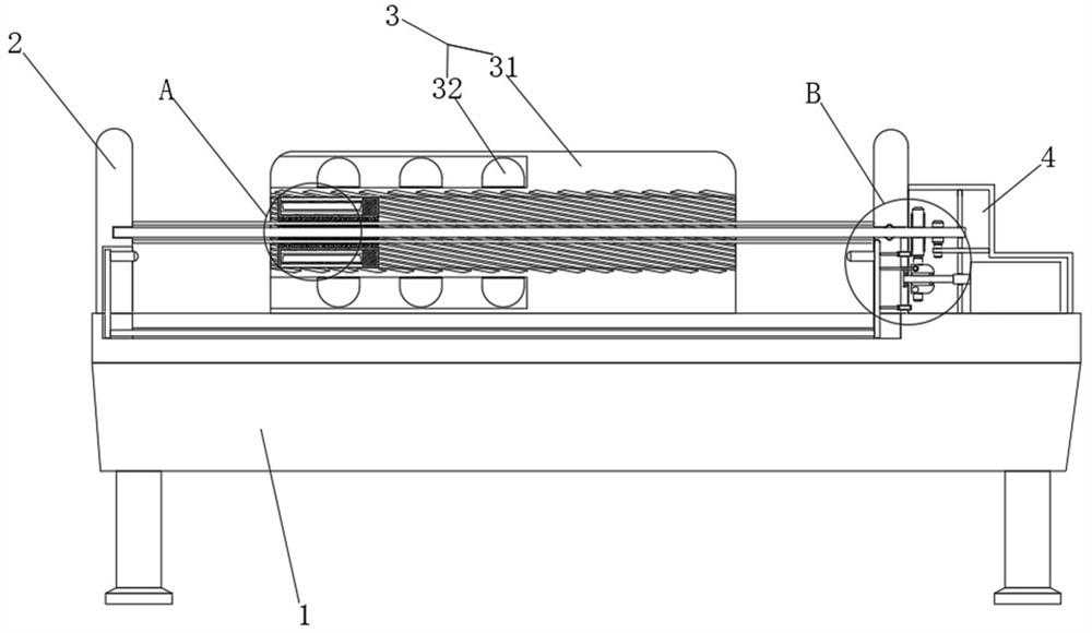
[0029] see Figure 1-4 , a fully degaussing device for electronic communication equipment, comprising a device base 1, two support plates 2 set on the top of the device base 1, a degaussing mechanism 3 set between the two support plates 2 on the device base 1, and driving the electronic communication equipment in The active mechanism 4 in the degaussing mechanism 3 is active.
[0030] The degaussing mechanism 3 includes a degaussing shell 31 fixedly connected to the top of the device base 1 , a degaussing channel is provided in the middle of the degaussing shell 31 , and a degaussing channel distributed around the degaussing channel and used to accommodate the degaussing coil 32 is arranged inside the degaussing shell 31 One end of the degaussing slot communicates with the outside world.
[0031] The movable mechanism 4 includes a driving shaft 41 that is rotatably connected to the surface of the support plate 2, and a receiving mechanism 42 is arranged on the surface of the ...
Embodiment 2
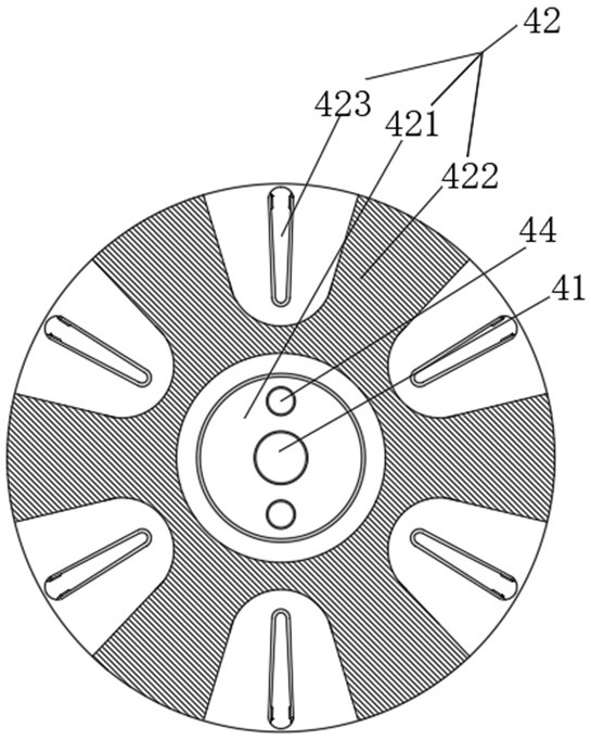
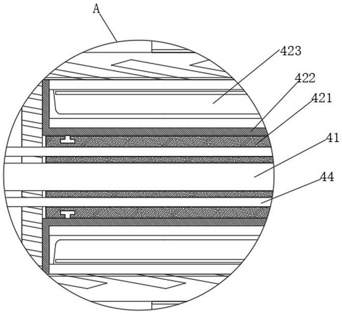
[0034] see Figure 2-3 The storage mechanism 42 includes a movable column 421 that is threadedly connected to the surface of the driving shaft 41. The entire surface of the driving shaft 41 is provided with threads for driving the movable column 421 to move. The surface of the movable column 421 is movably connected with a receiving column 422, and the receiving column 422 The surface of the through hole is provided with a thread-like pattern that matches the internal thread groove of the degaussing channel, the center of the receiving column 422 is provided with a through hole that is adapted to the movable column 421, and the inner wall of the through hole passes through the slider and the chute. It is slidably connected to the surface of the movable column 421. The surface of the receiving column 422 is evenly provided with a receiving cavity that opens from the center to the outside, and the interior of the receiving cavity is fixedly connected with a receiving bag 423, and...
Embodiment 3
[0037] see Figure 4 The drive mechanism 43 includes a drive housing 431 fixedly connected to the top of the device base 1, one end of the drive shaft 41 extends to the inside of the drive housing 431, and the end surface of the drive shaft 41 is sequentially fixed from the support plate 2 to the drive housing 431. A driving large gear 432 and a driving pinion 433 are connected, a motor is provided on the top surface of the device base 1 inside the driving housing 431, and a linkage shaft 434 is fixedly connected to the output end of the motor, and the end of the linkage shaft 434 away from the motor is supported by bearings and supports The surface of the plate 2 is rotatably connected, the surface of the linkage shaft 434 is slidably connected with the sliding slot through the slider, and a push column 435 is slidably connected to the surface of the push column 435. , a steering gear 437 meshing with the driving pinion 433 is rotatably connected to the inside of the driving ...
PUM
 Abstract
Description
Claims
Application Information
 - R&D
- Intellectual Property
- Life Sciences
- Materials
- Tech Scout
- Unparalleled Data Quality
- Higher Quality Content
- 60% Fewer Hallucinations
Browse by: Latest US Patents, China's latest patents, Technical Efficacy Thesaurus, Application Domain, Technology Topic, Popular Technical Reports.
© 2025 PatSnap. All rights reserved.Legal|Privacy policy|Modern Slavery Act Transparency Statement|Sitemap|About US| Contact US: help@patsnap.com


