
Communication power supply cabinet

A communication power supply cabinet and cabinet technology, applied in the field of communication, can solve the problems of limited maintenance operation space, poor contact, interruption of communication circuits, etc., and achieve the effects of strong practicability, easy maintenance, and easy maintenance.

Pending Publication Date: 2022-03-22
深圳市国网迈腾电力科技股份有限公司
View PDF0 Cites 0 Cited by
  • Summary
  • Abstract
  • Description
  • Claims
  • Application Information

AI Technical Summary

Problems solved by technology

[0002] The communication power supply system is the heart of the communication system. A stable and reliable communication power supply system is the key to ensure the safe and reliable operation of the communication system. The communication circuit is interrupted and the communication system is paralyzed, resulting in great economic and social benefit losses
[0003] In the existing communication power supply system, the power supply cabinet is often used for power supply. The existing communication power supply cabinet is loaded with many power devices, and these power devices will inevitably suffer from aging or poor contact when they are used for a long time. Therefore, frequent maintenance is required. Since the cabinet body is directly opened with an inspection door, the maintenance is carried out inside the cabinet body through the inspection door. The maintenance operation space is limited, and the connecting wires are messy, which is inconvenient for maintenance.

Method used


Image

  • Communication power supply cabinet
  • Communication power supply cabinet
  • Communication power supply cabinet

Examples


Embodiment Construction

[0021] In order to make the object, technical solution and advantages of the present invention clearer, the present invention will be described in further detail below in conjunction with the drawings and embodiments; in the drawings or descriptions, similar or identical parts use the same symbols, and in actual In application, the shape, thickness or height of each part can be enlarged or reduced. The various embodiments listed in the present invention are only used to illustrate the present invention, and are not intended to limit the scope of the present invention. Any obvious modifications or changes made to the present invention do not depart from the spirit and scope of the present invention.

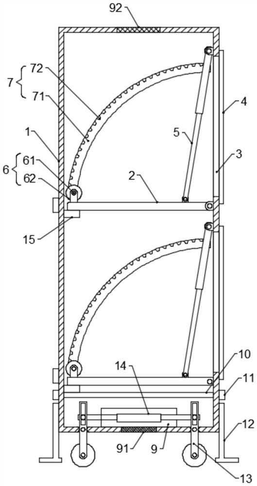
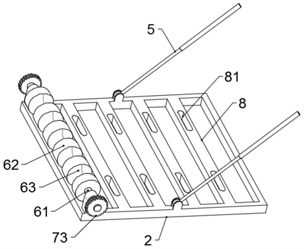
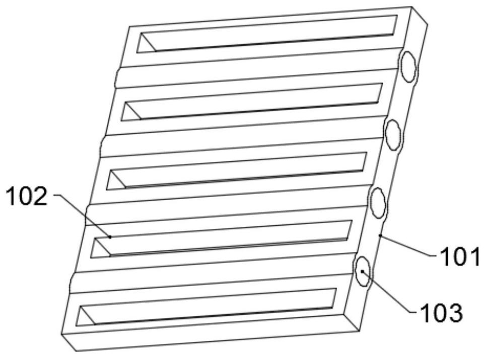
[0022] In one embodiment, such as figure 1 and figure 2 As shown, a communication power supply cabinet includes a cabinet body 1 and a supporting installation part 2. At least one inspection port 3 is provided on the outer wall of the cabinet body 1. The body 1 is hinged close...


PUM


Abstract

The invention discloses a communication power supply cabinet, and relates to the technical field of communication, the power supply cabinet comprises a cabinet body and a bearing installation part, the outer wall of the cabinet body is provided with at least one maintenance port, the bearing installation part is arranged in the cabinet body, and the side part of the bearing installation part is hinged to the inner wall, close to the maintenance port, of the cabinet body; the device further comprises a driving piece, a winding roller assembly and a transmission assembly. The winding roller assembly is arranged at the end, away from the overhaul port, of the bearing installation piece and used for winding and combing a wire connected with the communication power supply device. The driving part is arranged on the inner wall of the cabinet body and is used for driving the bearing mounting part to rotate around the hinged part of the bearing mounting part and the side wall of the cabinet body; the transmission assembly is arranged in the cabinet body and used for driving the winding roller assembly to rotate when the bearing installation piece rotates. The power supply device turnover device is simple in structure, the power supply device can be turned over to the cabinet door to facilitate maintenance, and in the turnover process, a wire of the power supply device is loosened or tensioned, so that subsequent disassembly is facilitated, and looseness of the wire after installation is avoided; operation is convenient and practicality is high.

Description

technical field [0001] The invention relates to the technical field of communication, in particular to a communication power supply cabinet. Background technique [0002] The communication power supply system is the heart of the communication system. A stable and reliable communication power supply system is the key to ensure the safe and reliable operation of the communication system. The communication circuit is interrupted and the communication system is paralyzed, resulting in great economic and social benefit losses. [0003] In the existing communication power supply system, the power supply cabinet is often used for power supply. The existing communication power supply cabinet is loaded with many power devices, and these power devices will inevitably suffer from aging or poor contact when they are used for a long time. Therefore, frequent maintenance is required. Since the cabinet body is directly opened with an inspection door, the inspection door is used for inspec...

Claims


Application Information

Patent Timeline
IPC IPC(8): H02B1/30H02B1/34H02B1/56
CPCH02B1/305H02B1/34H02B1/30H02B1/565
Inventor 张福阔
Owner 深圳市国网迈腾电力科技股份有限公司
Learn More