Swivel joint and operation machine

A technology for rotary joints and working machinery, applied in the direction of connection, rotating current collectors, current collectors, etc., can solve the problems of easy damage of electric slip rings, high maintenance cost and high cost of electric slip rings, and achieves reduction of processing costs and simple structure. , the effect of low cost

Pending Publication Date: 2022-03-22
BEIJING SANY INTELLIGENT MFG TECH CO LTD
View PDF0 Cites 0 Cited by
  • Summary
  • Abstract
  • Description
  • Claims
  • Application Information

AI Technical Summary

Problems solved by technology

[0004] Therefore, the technical problem to be solved by the present invention is to overcome the defects of high cost, easy damage of electric slip ring and high maintenance cost of electric slip ring caused by electric slip ring connecting internal and external cables in the rotary joint in the prior art, so as to provide a rotary joint and work machinery

Method used


Image

  • Swivel joint and operation machine
  • Swivel joint and operation machine
  • Swivel joint and operation machine

Examples


Embodiment 1

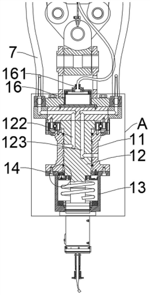
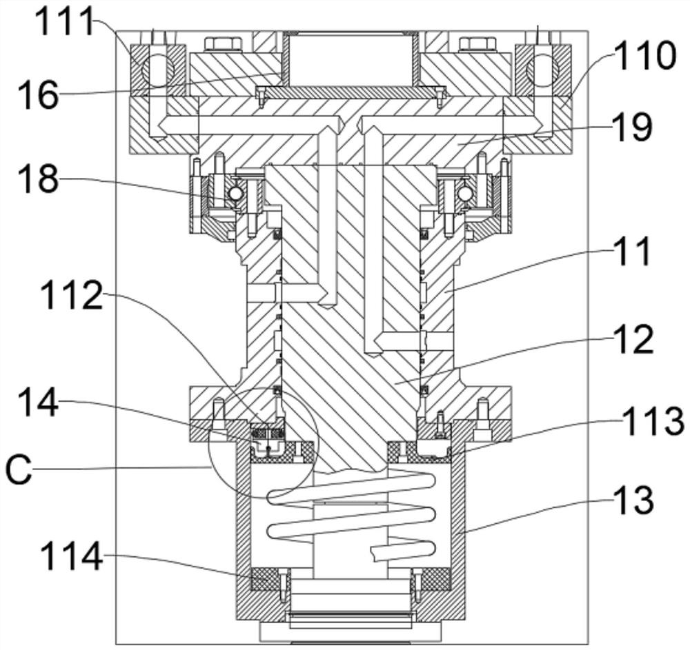
[0039] This embodiment provides a rotary joint 1, such as Figure 1 to Figure 5 As shown, it includes a shaft sleeve 11, a main shaft 12 and a wire storage box 13. Among them, the shaft sleeve 11 is set outside the main shaft 12, and the main shaft 12 is rotatably arranged in the shaft sleeve 11; the main shaft 12 is provided with a wire hole 121; the wire storage box 13 is fixedly connected to the shaft sleeve 11; the wire storage box 13 There is an accommodating chamber for storing the cables 5, and the wire storage box 13 is provided with a first outlet 131 communicating with the accommodating chamber.

[0040]When the swivel joint 1 of this structure is used, it is connected to the working device 2, and the cable 5 is passed through the wire hole 121 of the main shaft 12 and the wire storage box 13, and a section of loose cable 5 is stored in the wire storage box 13. , when the main shaft 12 rotates relative to the shaft sleeve 11, the wire storage box 13 is fixed relativ...

Embodiment 2

[0061] This embodiment provides a working machine, such as Figure 6 and Figure 7 As shown, it includes the rotary joint 1 and the working device 2 in the first embodiment, and the shaft sleeve 11 is connected to the working device 2 .

[0062] For the working machine with this structure, the cable 5 in the junction box 16 can rotate with the cable 5 inside the main shaft 12, providing a turning margin for the relative rotation of the upper and lower cables 5, preventing the cable 5 from twisting itself, effectively protecting the cable 5, and preventing the cable 5 from being damaged. and the slack section cable 5 is located in the wire storage box 13, and will not be wound and scratched against the external mechanism of the wire storage box 13, so as to effectively protect the cable 5 and prolong the service life of the cable 5. The swivel joint 1 accommodates a section of slack cable 5 through the wire storage box 13 to provide a swivel margin for the relative rotation of...


PUM


Abstract

The invention provides a swivel joint and an operation machine, and the swivel joint comprises a shaft sleeve, a main shaft and a wire storage box. Wherein the wire storage box is provided with a containing cavity, and a first wire outlet communicated with the containing cavity is formed in the wire storage box. When in use, the swivel joint is connected to a working device, a cable penetrates through the wire passing hole of the main shaft and the wire storage box, a section of loose cable is stored in the wire storage box, and when the main shaft rotates relative to the shaft sleeve, the loose cable in the junction box provides rotation allowance for relative rotation of an upper cable and a lower cable, so that the cable is prevented from twisting, the cable is effectively protected, and the service life of the cable is prolonged. Cable damage is prevented; the loose section cable is located in the cable storage box and cannot wind and scrape an external mechanism of the cable storage box, so that the cable is effectively protected, and the service life of the cable is prolonged. The swivel joint accommodates a section of loose cable through the cable storage box, provides swivel allowance for relative rotation of the upper and lower cables, is simple in structure, is not easy to damage, does not need to be provided with an electric slip ring, is low in cost, and can effectively reduce maintenance cost.

Description

technical field [0001] The invention relates to the technical field of rotary joints, in particular to a rotary joint and an operating machine. Background technique [0002] The existing rotary joint includes an electric slip ring and a joint body rotatably arranged at one end of the electric slip ring. The electric slip ring includes a casing, a conductive ring and a brush. One end of the external cable is connected to the conductive ring, and one end of the internal cable is connected to the brush. The other end extends to the bottom of the joint body through the through hole in the middle of the joint body. The bottom of the swivel joint is connected to the working device, and the internal cable at the bottom is connected to the working device to realize signal transmission. The cable on the side of the working device rotates with the joint body through the setting of the electric slip ring , to prevent the twisting of the cable when the connector body is turned, and prev...

Claims


Application Information

Patent Timeline
Patent Type & Authority Applications(China)
IPC IPC(8): H01R39/08H01R39/18F16L39/06
CPCH01R39/08H01R39/18F16L39/06
Inventor 张福鹏元跃翔安贵平
Owner BEIJING SANY INTELLIGENT MFG TECH CO LTD
Why Eureka
Try Eureka