Electronic control device
An electronic control device and map information technology, applied in non-electric variable control, traffic control system, control/regulation system, etc., can solve problems such as inability to perform route search
- Summary
- Abstract
- Description
- Claims
- Application Information
AI Technical Summary
Problems solved by technology
Method used
Image

Examples
no. 1 Embodiment approach
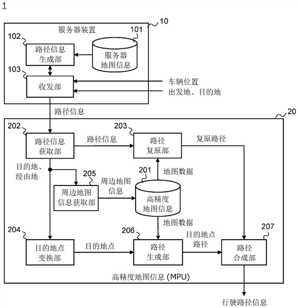
[0025] figure 1 It is a functional block diagram showing an example of the functional configuration of the route search system 1 according to the first embodiment of the present invention. The route search system 1 of the present embodiment is composed of a server device 10 and a high-precision map management device 20 . The server device 10 is installed in a predetermined place such as a data center. The high-resolution map management device 20 is a type of electronic control unit (ECU: Electronic Control Unit) mounted on a vehicle, and is configured using, for example, an MPU (Micro Processing Unit, micro processing unit). The server device 10 and the high-resolution map management device 20 are connected to each other via a mobile phone line or a public communication network such as the Internet. In this system, a plurality of vehicles equipped with the high-resolution map management device 20 are managed.
[0026] The server device 10 includes a server map database (her...
no. 2 Embodiment approach
[0065] Next, a route search system according to a second embodiment of the present invention will be described. The path search system of this embodiment has the same figure 1 The same functional configuration as the route search system 1 of the first embodiment described above. Therefore, the following uses figure 1 The functional configuration of the route search system of this embodiment will be described.
[0066] Figure 5 It is a figure explaining the outline|summary of 2nd Embodiment of this invention. exist Figure 5 In , the range indicated by reference numeral 61 represents the map range covered by the server map information stored in the server map DB 101 in the server device 10 (hereinafter referred to as "server map range"). In addition, the range indicated by reference numeral 62 represents the map range covered by the high-resolution map information stored in the high-precision map DB 201 in the high-precision map management device 20 (hereinafter referred ...
no. 3 Embodiment approach
[0083] Next, a route search system according to a third embodiment of the present invention will be described. The path search system of this embodiment has the same figure 1 The same functional configuration as the route search system 1 of the first embodiment described above. Therefore, the following uses figure 1 The functional configuration of the route search system of this embodiment will be described. Hereinafter, the description of the case where the same processing as in the first embodiment is performed will be omitted. In this embodiment, an example of a case in which the departure location is different from the current location of the vehicle will be described.
[0084]In this embodiment, a case where the user calls a taxi to an arbitrary departure point facility and moves to an arbitrary destination facility by operating an information terminal will be described as an example. Users can designate any facility as a departure point as well as a destination. Des...
PUM
 Abstract
Description
Claims
Application Information
 - Generate Ideas
- Intellectual Property
- Life Sciences
- Materials
- Tech Scout
- Unparalleled Data Quality
- Higher Quality Content
- 60% Fewer Hallucinations
Browse by: Latest US Patents, China's latest patents, Technical Efficacy Thesaurus, Application Domain, Technology Topic, Popular Technical Reports.
© 2025 PatSnap. All rights reserved.Legal|Privacy policy|Modern Slavery Act Transparency Statement|Sitemap|About US| Contact US: help@patsnap.com