Existing type infrared induction lamp
An infrared induction and sensor technology, applied in lighting and heating equipment, lighting devices, fixed lighting devices, etc., can solve the problems of inconvenience, small movement range, and inability to adjust the height of the lamp body, and achieve the effect of improving the efficiency of installation and use
- Summary
- Abstract
- Description
- Claims
- Application Information
AI Technical Summary
Problems solved by technology
Method used
Image
Examples
Embodiment 1
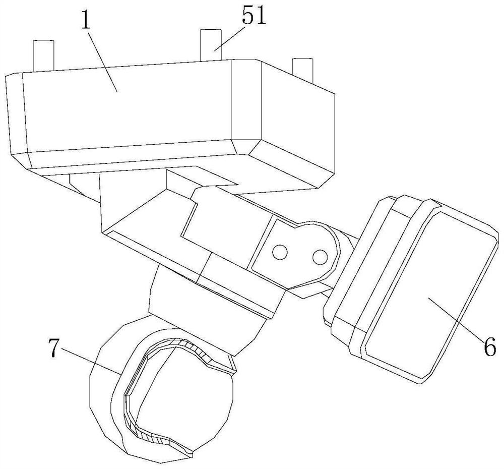
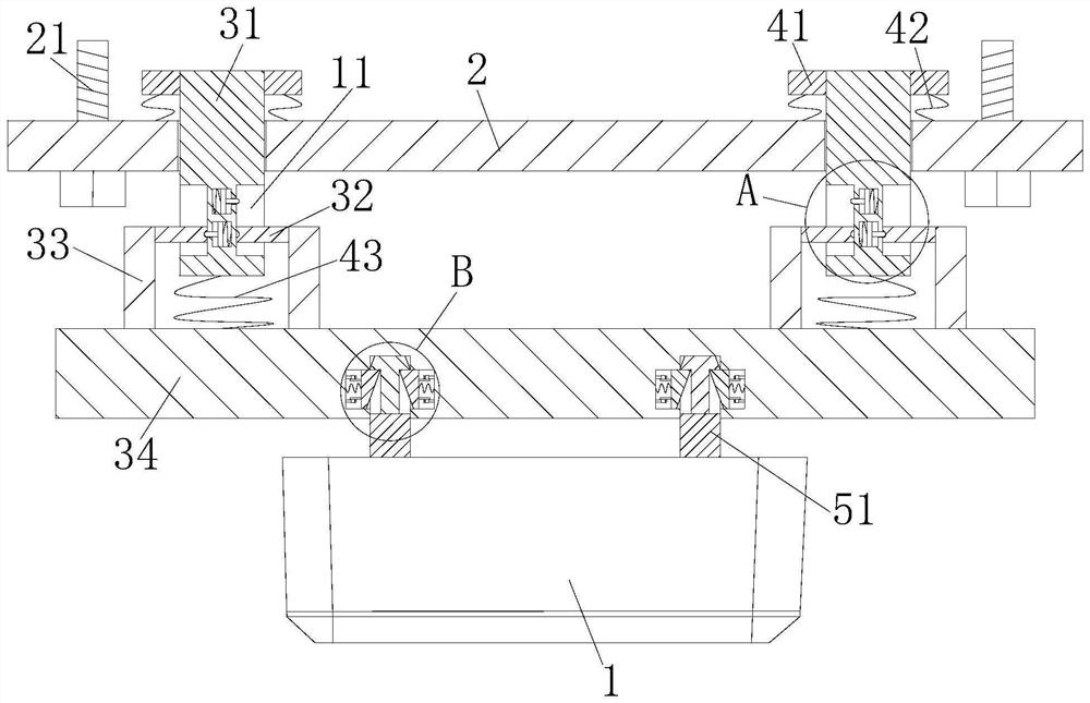
[0032] Such as Figure 1 to Figure 4 As shown, an infrared induction lamp that is easy to install according to the present invention includes a lamp body 1, a mounting plate 2 and an adjustment mechanism; the lamp body 1 is provided with a motor (not shown), and the output end of the motor An inductor 7 is provided; a control module (not shown in the figure) is provided in the lamp body 1, and the control module is electrically connected with the lamp body 1, the motor and the inductor 7; the mounting plate 2 is arranged on the lamp body 1 above;
[0033] Preferably, the control module includes a signal amplification and processing circuit module; a lighting lamp 6 is provided at the bottom of the lamp body 1; the lighting lamp 6 is set at an adjustable angle;
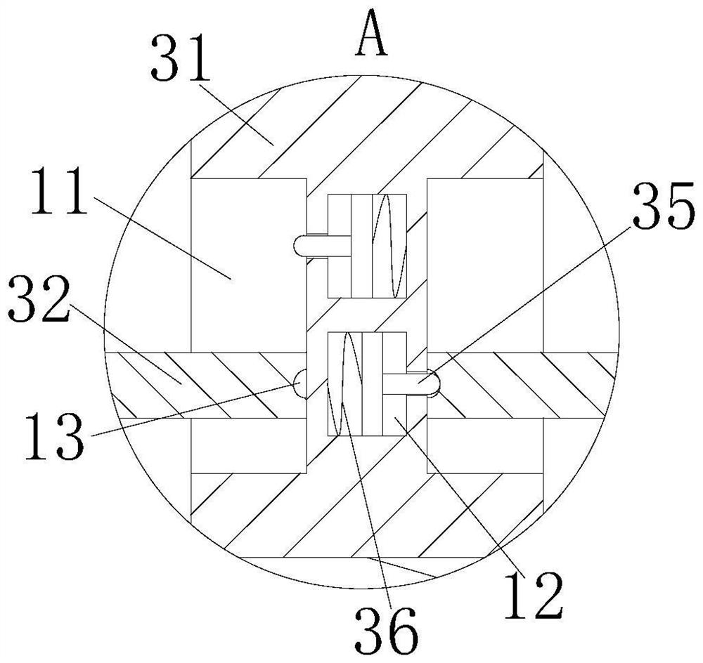
[0034]The adjustment mechanism includes a fixed block 31, a slide block 32, a fixed frame 33, a support plate 34, an extruding rod 35 and a first spring 36; the top end of the fixed block 31 is arranged inside the mou...
Embodiment 2
[0039] see Figure 5 As shown in Comparative Example 1, as another embodiment of the present invention, the bottom of the support plate 34 is symmetrically fixed with a handle 8; during work, by setting the handle 8, the staff can lower the height of the lamp body 1 to improve The practicality of the infrared sensor lamp.
[0040] Working principle: when the device is used, first install the support plate 34 and the installation plate 2 on the ceiling, and finally install and fix the lamp body 1 on the bottom of the support plate 34, and insert the insertion rod 52 into the installation hole 14, so that the insertion rod 52 The outer wall of the end is in contact with the outer wall of the clamping block 53, so that the clamping block 53 slides inside the square groove 15 after being squeezed by the insertion rod 52, and simultaneously squeezes the fourth spring 54, and the insertion rod 52 is completely installed into the installation hole 14. Finally, due to the return acti...
PUM
 Abstract
Description
Claims
Application Information
 - Generate Ideas
- Intellectual Property
- Life Sciences
- Materials
- Tech Scout
- Unparalleled Data Quality
- Higher Quality Content
- 60% Fewer Hallucinations
Browse by: Latest US Patents, China's latest patents, Technical Efficacy Thesaurus, Application Domain, Technology Topic, Popular Technical Reports.
© 2025 PatSnap. All rights reserved.Legal|Privacy policy|Modern Slavery Act Transparency Statement|Sitemap|About US| Contact US: help@patsnap.com


