Suspension type material conveying system for material shed
A conveying system and hanging technology, which is applied in the direction of conveyors, conveyor objects, mechanical conveyors, etc., can solve the problem of low usable volume of material sheds, improve volume utilization, increase usable volume, and improve usability The effect of volume
- Summary
- Abstract
- Description
- Claims
- Application Information
AI Technical Summary
Problems solved by technology
Method used
Image
Examples
specific Embodiment 1
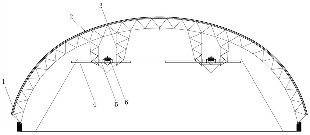
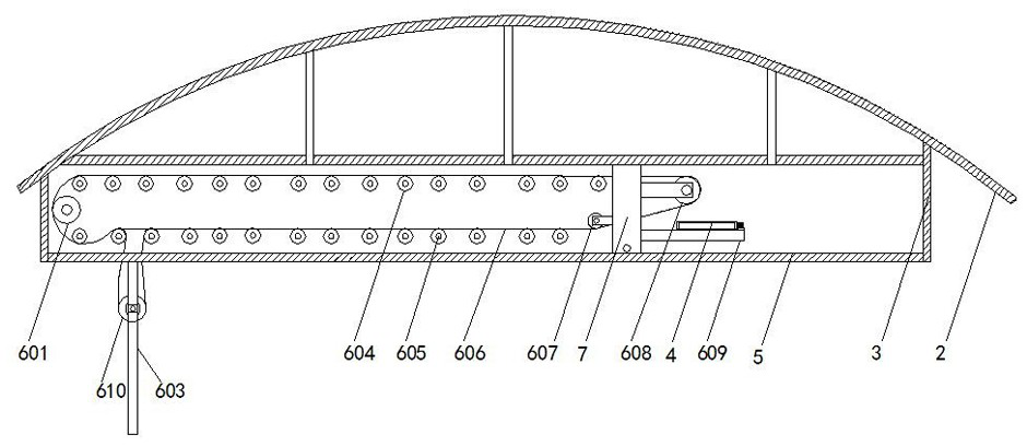
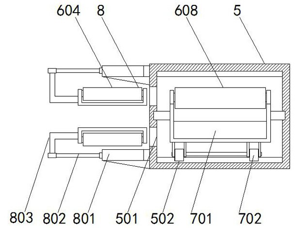
[0038] Please refer to Figure 1 to Figure 5 shown.
[0039]The suspended material conveying system of the present embodiment includes a support gallery 5, the support gallery 5 is used to hang on the top of the material shed 2, and the support gallery 5 extends longitudinally along the material shed 2, so as to cover as much as possible along it at the top of the material shed 2. The maximum length path setting of the stockyard, wherein, vertically refers to that if the stockyard has a certain length, the support gallery 5 is longitudinal along the length direction of the stockyard, and if the stockyard is circular, then the support gallery 5 can be made along the length direction of the stockyard. The axis of the stockyard is set, and the direction of the support gallery 5 on the axis of the stockyard is the longitudinal direction, so that the support gallery 5 can cover the top of the stockyard as much as possible, so that the materials can finally enter the stockyard for s...
specific Embodiment 2
[0055] In Embodiment 1, a tension roller 610 is provided. Therefore, the tension roller 610 inevitably occupies a certain space in the moving direction of the driving trolley 7, so that the driving trolley is provided with the end of the driven roller 601 on the supporting gallery 5. There is a large dead space that is difficult to move in the past. In order to maximize the movement of the driving trolley 7 in the conveying direction and reduce the above dead space, the difference from the first embodiment is that the combined Figure 6 As shown, a vertically suspended installation frame 603 is provided at one end of the support gallery 5 for setting the driven roller 601, and the driven roller 601 is vertically slidably installed on the installation frame 603, and the sliding installation at this place can be implemented The sliding installation in the first is the same, and the driven roller 601 can slide freely on the mounting frame 603. Like this, the driven roller 601 is s...
specific Embodiment 3
[0059] In the second embodiment, the driven roller 601 is vertically slidably set. As mentioned above, due to the long distance required in the conveying direction of the conveying mechanism 6 in industrial applications, when the conveying belt 606 is stored in the vertical direction, Or there is a situation where the height is not enough, combined with Figure 7 As shown, multiple installation frames 603 can be provided at one end of the supporting gallery 5 for setting the driven roller 601, and correspondingly, one driven roller 601 is vertically slidably installed on each installation frame 603, The tensioning and accommodating functions of the entire feeding mechanism 6 to the feeding belt 606 are greatly improved.
PUM
 Abstract
Description
Claims
Application Information
 - R&D
- Intellectual Property
- Life Sciences
- Materials
- Tech Scout
- Unparalleled Data Quality
- Higher Quality Content
- 60% Fewer Hallucinations
Browse by: Latest US Patents, China's latest patents, Technical Efficacy Thesaurus, Application Domain, Technology Topic, Popular Technical Reports.
© 2025 PatSnap. All rights reserved.Legal|Privacy policy|Modern Slavery Act Transparency Statement|Sitemap|About US| Contact US: help@patsnap.com


