
Multi-numerical control machine tool combined machining center of intelligent terminal camera ring

A technology of CNC machine tools and intelligent terminals, applied in metal processing, metal processing equipment, manufacturing tools, etc., can solve the problems of increasing production costs, affecting the processing efficiency of camera rings, affecting the sales effect of finished camera rings, etc. The effect of reducing the amount of use

Active Publication Date: 2022-03-18
东莞市领亿精密金属有限公司
View PDF11 Cites 3 Cited by
  • Summary
  • Abstract
  • Description
  • Claims
  • Application Information

AI Technical Summary

Problems solved by technology

[0003] However, in the existing technology, the camera ring of the smart terminal needs to be processed by various machine tools in the actual processing process, and due to the limitation of the structure of the machine tool, when the camera ring is sequentially processed by various machine tools, it needs to use more auxiliary tools. The transfer of equipment will affect the actual processing efficiency of the camera ring, and at the same time increase the actual production cost, which will easily affect the actual sales effect of the finished camera ring

Method used


Image

  • Multi-numerical control machine tool combined machining center of intelligent terminal camera ring
  • Multi-numerical control machine tool combined machining center of intelligent terminal camera ring
  • Multi-numerical control machine tool combined machining center of intelligent terminal camera ring

Examples


Embodiment 1

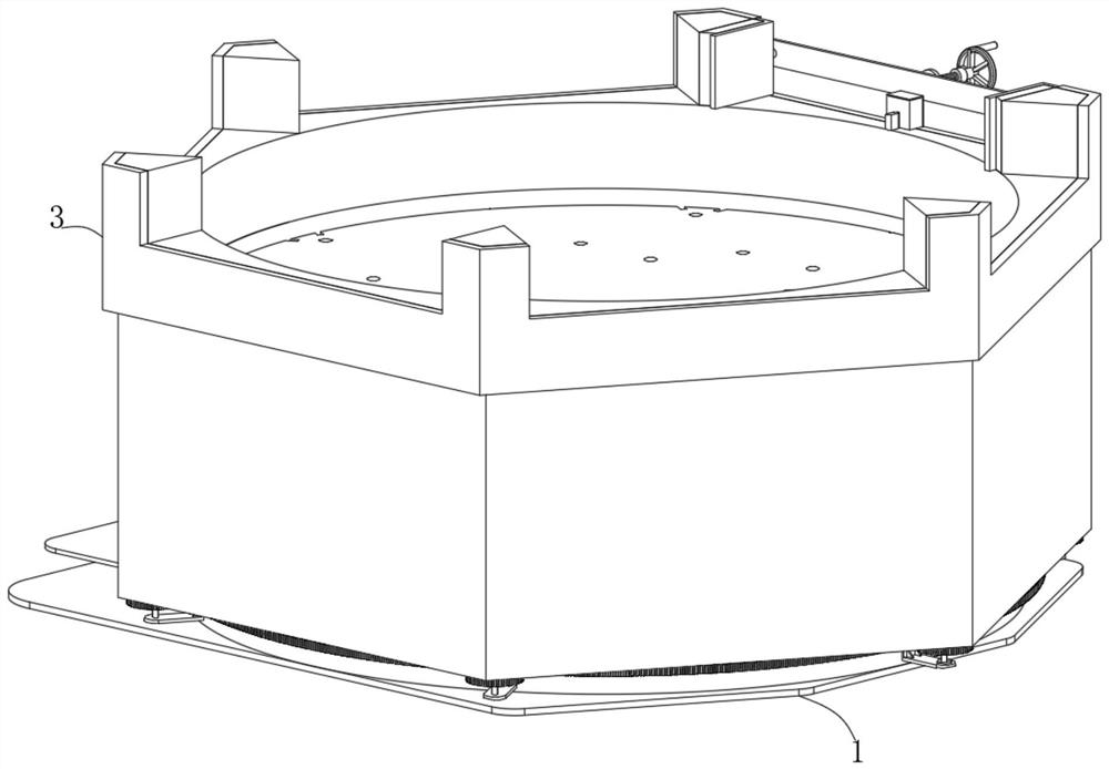
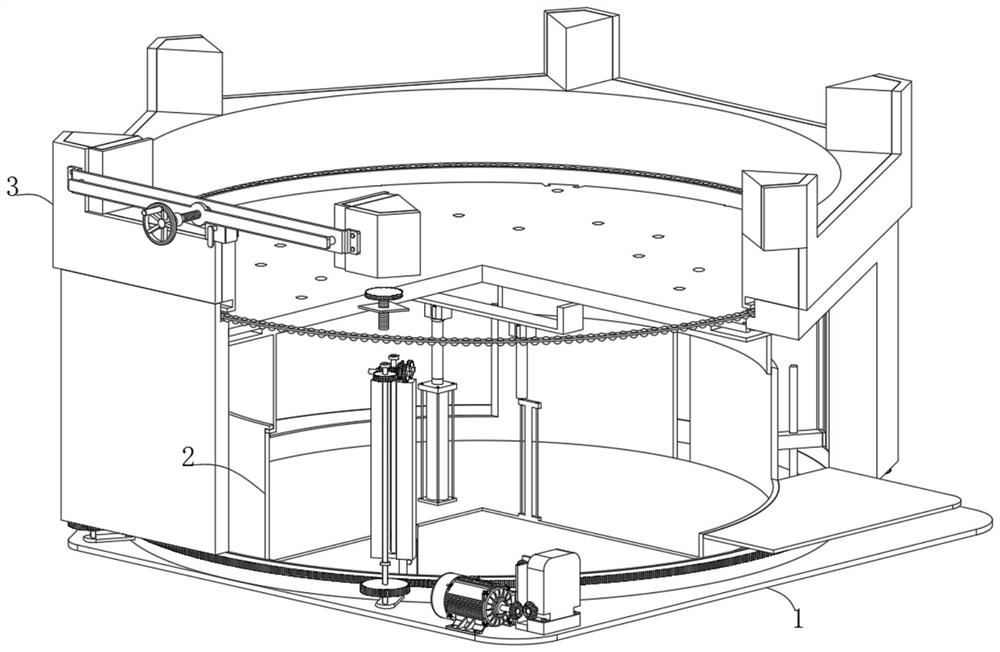
[0033] refer to Figure 1-Figure 10: A combined machining center of multiple CNC machine tools with an intelligent terminal camera ring, comprising: a limit mechanism 1, a support mechanism 2 and a positioning mechanism 3, the limit mechanism 1 includes a base 101, a driving part and a lifting part, and the base 101 is set up Provide the installation basis for setting other functional components of the equipment, and at the same time enable the equipment to be placed firmly in the designated use position. The outer surface of the base 101 is slidingly sleeved with a ring gear 110. The setting of the ring gear 110 cooperates with the first gear 109 so that the motor 103 can effectively drive the connecting gear. The moving shaft 111 rotates, and the bottom frame 102 is fixedly connected to the top of the base 101. The bottom frame 102 is set up to facilitate the installation and setting of other functional parts of the equipment. The top of the bottom frame 102 is equidistantly ...


PUM


Abstract

The multi-numerical-control-machine-tool combined machining center for the intelligent terminal camera ring comprises a limiting mechanism, the limiting mechanism comprises a base, a driving component and a lifting component, the outer surface of the base is slidably sleeved with a gear ring, the top of the base is fixedly connected with a bottom frame, and a plurality of positioning holes are formed in the top of the bottom frame at equal intervals; five mounting grooves are formed in the inner surface wall of the bottom frame at equal intervals. During use, according to the actual overall structure size of the machine tool, the machine tool can be effectively fixed to the tops of carrier plates of multiple devices through the mounting holes, the actual use height of the carrier frame is effectively adjusted by controlling the hydraulic rods, the actual use height of the machine tool on the tops of the carrier plates can be effectively adjusted, and meanwhile the starting motor is controlled to start the machine tool. Therefore, the motor can effectively drive the speed reducer to operate through the linkage bevel gear, and the operating speed reducer can drive the limiting shaft to rotate through the third bevel gear, the positioning shaft and the second bevel gear.

Description

technical field [0001] The invention belongs to the technical field of machine tool combination equipment, and specifically relates to a multi-NC machine tool combined machining center with an intelligent terminal camera ring. Background technique [0002] Machine tools refer to machines that manufacture machines, also known as machine tools or tool machines, which are customarily referred to as machine tools and are generally divided into metal cutting machine tools, forging machine tools and woodworking machine tools. [0003] However, in the existing technology, the camera ring of the smart terminal needs to be processed by various machine tools in the actual processing process, and due to the limitation of the structure of the machine tool, when the camera ring is sequentially processed by various machine tools, it needs to use more auxiliary tools. The transfer of equipment will affect the actual processing efficiency of the camera ring, and at the same time increase th...

Claims


Application Information

Patent Timeline
Patent Type & Authority Applications(China)
IPC IPC(8): B23Q41/04
CPCB23Q41/04
Inventor 郑拱昌
Owner 东莞市领亿精密金属有限公司
Learn More