Eureka AIR delivers breakthrough ideas for toughest innovation challenges, trusted by R&D personnel around the world.

Resource object allocation method and device based on live broadcast room, equipment and storage medium

A resource object and live broadcast room technology, applied in the field of live broadcast, can solve problems such as insufficient allocation of resource objects, inability of users to complete resource object occupancy, and inability to continue business processes, etc., to increase background burden, improve allocation efficiency, and improve utilization rate effect

Active Publication Date: 2022-03-15
GUANGZHOU BAIGUOYUAN NETWORK TECH
View PDF12 Cites 1 Cited by
  • Summary
  • Abstract
  • Description
  • Claims
  • Application Information

AI Technical Summary

Problems solved by technology

[0003] At present, there are generally anchors in the live broadcast room. The anchor is the direct participant of state maintenance and state synchronization. Without the anchor, the user cannot complete the occupation of resource objects.
In this way, the anchor side will perform a lot of tasks, and needs to constantly interact with the background, and even need to introduce a state machine to achieve the purpose of maintaining various states. The anchor side APP will become very heavy, and the energy consumption will also increase. An exception will cause the entire business process to fail
Therefore, the existing resource object allocation scheme in the live broadcast room is not perfect and needs to be improved

Method used


Image

  • Resource object allocation method and device based on live broadcast room, equipment and storage medium
  • Resource object allocation method and device based on live broadcast room, equipment and storage medium
  • Resource object allocation method and device based on live broadcast room, equipment and storage medium

Examples


Embodiment Construction

[0024] The present invention will be further described in detail below in conjunction with the accompanying drawings and embodiments. It should be understood that the specific embodiments described here are only used to explain the present invention, but not to limit the present invention. In addition, it should be noted that, for the convenience of description, only some structures related to the present invention are shown in the drawings but not all structures. In addition, the embodiments and the features in the embodiments of the present invention can be combined with each other under the condition of no conflict.

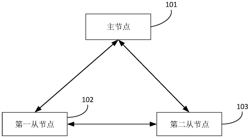
[0025] figure 1 It is a scene architecture diagram of an application scenario to which a method for allocating resource objects based on a live broadcast room is applicable according to an embodiment of the present invention. Specifically, refer to figure 1 , in this application scenario, the service side corresponding to the live broadcast platform may inc...


PUM


Abstract

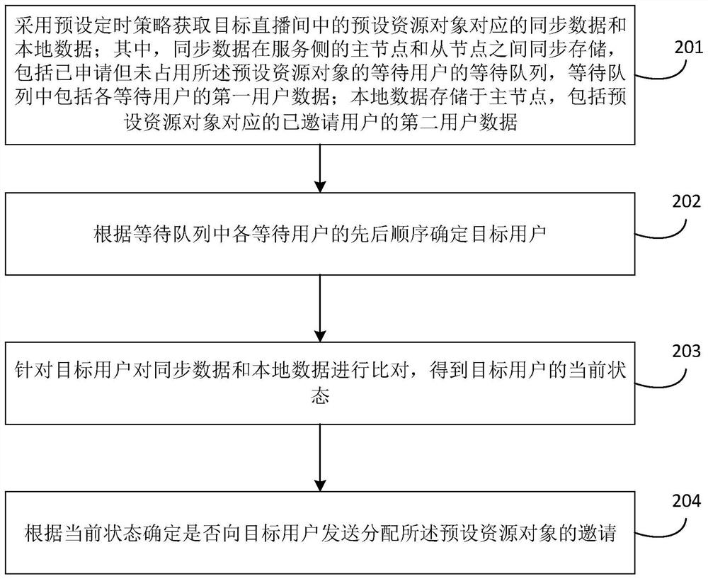
The embodiment of the invention discloses a resource object allocation method and device based on a live broadcast room, equipment and a storage medium. The method comprises the steps that a master node of a service side obtains synchronous data and local data corresponding to a preset resource object in a target live broadcast room, and the synchronous data is synchronously stored in master and slave nodes and comprises a waiting queue of waiting users who have applied but do not occupy the preset resource object; the waiting queue comprises first user data of each waiting user, the local data is stored in the main node and comprises second user data of invited users corresponding to the preset resource object, determining a target user according to the waiting queue, comparing the synchronous data with the local data for the target user to obtain a current state of the target user, and sending the current state of the target user to the main node. And determining whether to send an invitation for allocating the preset resource object to the target user. Through adoption of the technical scheme, the server side can automatically realize reasonable allocation of the resource objects in the live broadcasting room, the burden of the anchor side terminal is reduced, and the allocation efficiency is improved.

Description

technical field [0001] The embodiments of the present invention relate to the field of live broadcast technology, and in particular, to a resource object allocation method, device, device, and storage medium based on a live broadcast room. Background technique [0002] The live broadcast room (referred to as the live broadcast room) is a virtual space in the live broadcast application (Application, APP) product, and is the main gathering place for users. One of its core functions is that users can use their respective terminal devices based on the microphone in the live broadcast room. Bits and other resource objects to communicate. Since a large number of users can exist in the live broadcast room at the same time, the resource object is a rare resource, that is, in the live broadcast room, when multiple people request to occupy the resource object, there will be a scene where multiple people snatch the same resource object at the same time. In order to avoid the high reso...

Claims


Application Information

Patent Timeline
Patent Type & Authority Applications(China)
IPC IPC(8): H04N21/2187H04N21/262H04N21/242H04N21/433
CPCH04N21/2187H04N21/26208H04N21/242H04N21/433
Inventor 智煜徽
Owner GUANGZHOU BAIGUOYUAN NETWORK TECH
Why Eureka
Eureka Blog
Learn More