Balanced converter
A balun, balanced terminal technology, used in waveguide-type devices, fixed transformers or mutual inductances, components of transformers/inductors, etc.
- Summary
- Abstract
- Description
- Claims
- Application Information
AI Technical Summary
Problems solved by technology
Method used
Image

Examples
Embodiment approach 1
[0034] (Outline of communication device)
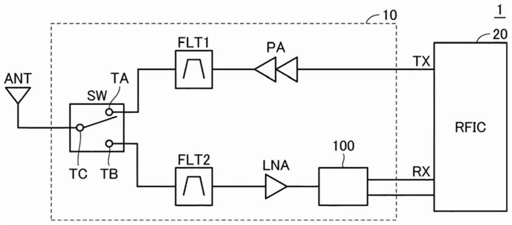
[0035] figure 1 It is a block diagram of the communication device 1 including the front-end circuit 10 to which the balun 100 according to Embodiment 1 is applied. refer to figure 1 , the communication device 1 includes an antenna ANT and an RFIC 20 as a signal processing circuit in addition to the front-end circuit 10 .
[0036] The RFIC 20 outputs a high-frequency signal to the transmission line TX, and radiates radio waves from the antenna ANT via the front-end circuit 10 . Moreover, RFIC20 receives the radio wave received by the antenna ANT from the receiving side line RX, processes this received signal, and transmits it to the circuit of a subsequent stage.
[0037]The front-end circuit 10 includes, in addition to the balun 100 , a switch SW, filters FLT1 , FLT2 , a power amplifier PA, and a low-noise amplifier LNA. The switch SW is used to switch between transmission and reception of radio waves in the antenna ANT. The swit...
Embodiment approach 2
[0083] In Embodiment 1 and its modifications, the case where the impedance of the device connected to the balanced terminal is equal to the impedance of the device connected to the unbalanced terminal, or the case where the impedance is higher has been described.
[0084] On the other hand, there are cases where the impedance of a device connected to a balanced terminal is made lower than the impedance of a device connected to an unbalanced terminal. In this case, generally, the number of windings of the coil forming the balanced line in the balun is reduced, the number of windings of the coil forming the unbalanced line is increased, or the capacitance of the capacitor C1 for wavelength adjustment is increased. achieve the desired impedance ratio. However, when the impedance on the balanced line side is low, it is necessary to further increase the degree of capacitive coupling between the unbalanced line and the balanced line in order to match the resonance frequency of the b...
Embodiment approach 3
[0104] In the example of the balun described in Embodiment 1 and Embodiment 2, as Figure 6 as well as Figure 13 As shown, a structure in which each line is formed of coils extending over two layers has been described. When this balun is used in a low frequency range, it may be necessary to further increase the line length of the coil. In this case, depending on the frequency of the object of use, the desired line length cannot be achieved in two layers, and the coil may need to be formed over more layers.
[0105] Here, as in the example of the balun in the present disclosure, in the case where external electrodes for connection with external devices are formed on the side surfaces of the dielectric substrate (refer to Figure 4 ), preferably the end connected to the external electrode in each line is located at the outer periphery of each dielectric layer. However, in the case of forming a spiral coil using an odd number (for example, three) of dielectric layers, the coi...
PUM
 Abstract
Description
Claims
Application Information
 - Generate Ideas
- Intellectual Property
- Life Sciences
- Materials
- Tech Scout
- Unparalleled Data Quality
- Higher Quality Content
- 60% Fewer Hallucinations
Browse by: Latest US Patents, China's latest patents, Technical Efficacy Thesaurus, Application Domain, Technology Topic, Popular Technical Reports.
© 2025 PatSnap. All rights reserved.Legal|Privacy policy|Modern Slavery Act Transparency Statement|Sitemap|About US| Contact US: help@patsnap.com