
Universal cement mortar test mold

A cement mortar and test mold technology, applied in the field of molds, can solve the problems of occupying laboratory space, affecting the efficiency of test piece forming and the accuracy of test piece size, and prone to slurry leakage, so as to reduce research costs and test sites. Occupation of the site, the realization of intensive utilization, the effect of reducing the probability of slurry leakage

Pending Publication Date: 2022-03-11
中冶武汉冶金建筑研究院有限公司 +1
View PDF3 Cites 1 Cited by
  • Summary
  • Abstract
  • Description
  • Claims
  • Application Information

AI Technical Summary

Problems solved by technology

[0002] In the relevant detection tests of cement-based materials, there are many types and quantities of tests related to mortar. Under normal conditions, different molds need to be made for different test contents, which brings various inconveniences: A large number of different molds occupy limited laboratory space, are expensive, and occupy scientific research costs; some relatively infrequent molds are idle for a long time, resulting in waste of resources; individual tests such as shear bond strength need to be completed. Hand-made foam blocks seriously affect the efficiency of specimen forming and the accuracy of specimen size, which in turn leads to large deviations in test results
In addition, traditional steel molds (cast iron molds) have problems of poor fixability and sealing, and slurry leakage is prone to occur during the molding process of test pieces, especially in vibration conditions, which also seriously affects the The quality of test piece production

Method used


Image

  • Universal cement mortar test mold
  • Universal cement mortar test mold
  • Universal cement mortar test mold

Examples


Embodiment Construction

[0024] In order to make the purposes, technical solutions and advantages of the embodiments of the present application clearer, the technical solutions in the embodiments of the present application will be clearly and completely described below in conjunction with the drawings in the embodiments of the present application. Obviously, the described embodiments It is a part of the embodiments of this application, not all of them. The components of the embodiments of the application generally described and illustrated in the figures herein may be arranged and designed in a variety of different configurations.

[0025] Accordingly, the following detailed description of the embodiments of the application provided in the accompanying drawings is not intended to limit the scope of the claimed application, but merely represents selected embodiments of the application. Based on the embodiments in this application, all other embodiments obtained by persons of ordinary skill in the art w...


PUM


Abstract

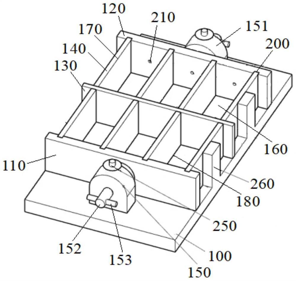
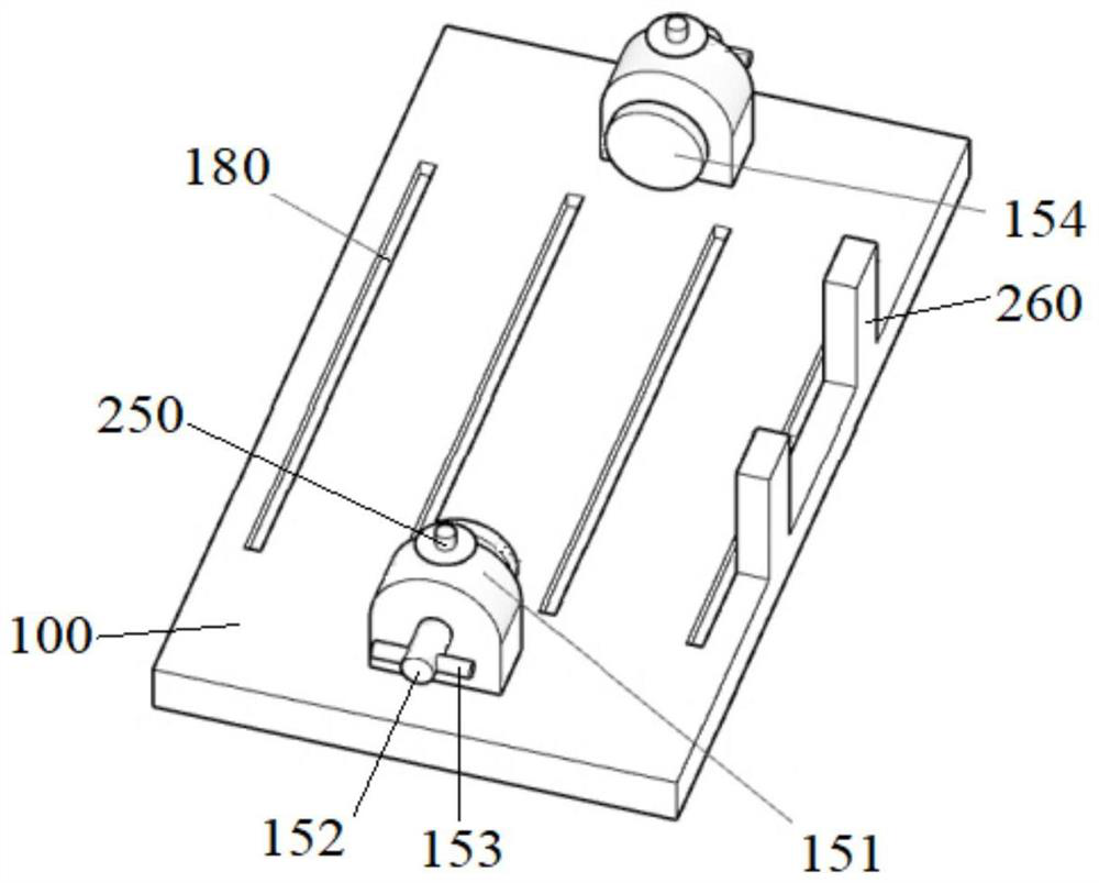
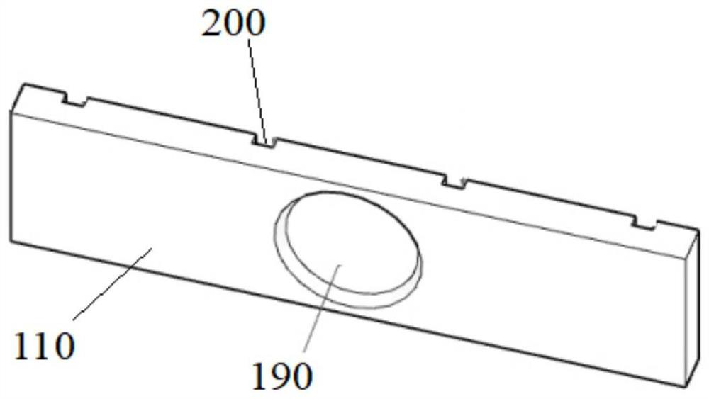
The invention discloses a universal cement mortar test mold and relates to the technical field of molds. The universal cement mortar test mold comprises a bottom plate, a front baffle, a rear baffle, at least one transverse partition plate, a plurality of longitudinal partition plates and two pressure applying devices connected to the two sides of the top face of the bottom plate correspondingly, and the front baffle and the rear baffle are oppositely arranged at the two ends of the top face of the bottom plate; the two pressure applying devices are used for pushing the front baffle and the rear baffle to move towards each other, the transverse partition plate is arranged between the front baffle and the rear baffle, one end of each longitudinal partition plate abuts against the transverse partition plate, and the other end of each longitudinal partition plate abuts against the front baffle, the rear baffle or the other transverse partition plate. The front baffle or the rear baffle, the bottom plate, the transverse partition plate and the longitudinal partition plates define a plurality of mold cavities with openings in the tops. According to the universal cement mortar test mold, the multiple mold cavities can be rapidly and efficiently isolated, the integrity, stability and sealing performance of mold assembly are effectively improved, and the mortar leakage probability is reduced.

Description

technical field [0001] The application relates to the technical field of molds, in particular, to a general-purpose cement mortar test mold. Background technique [0002] In the relevant detection tests of cement-based materials, there are many types and quantities of tests related to mortar. Under normal conditions, different molds need to be made for different test contents, which brings various inconveniences: A large number of different molds occupy limited laboratory space, are expensive, and occupy scientific research costs; some relatively infrequent molds are idle for a long time, resulting in waste of resources; individual tests such as shear bond strength need to be completed. Hand-made foam blocks seriously affect the efficiency of test piece forming and the accuracy of test piece size, which in turn leads to large deviations in test results. In addition, traditional steel molds (cast iron molds) have problems of poor fixability and sealing, and slurry leakage is...

Claims


Application Information

Patent Timeline
Patent Type & Authority Applications(China)
IPC IPC(8): G01N1/36
CPCG01N1/36G01N2001/366G01N2001/368
Inventor 张剑峰陈报红程铠刘仕琪张冰
Owner 中冶武汉冶金建筑研究院有限公司
Learn More