


Quick Research
Generate reliable direction feasibility study reports for your R&D in just a few steps.

Technical Q&A
Discover and master advanced knowledge NOW. Basics, ideas, possibilities, all at once.

Find Solutions
As an expert in R&D theories, this can generate solutions to your technical problems instantly.

Evaluate Feasibility
Analyze your overall solution with one click, know your potential R&D risks in advance.

Monitor Landscape
Get weekly tech updates, stay abreast of the latest tech innovations and key insights.
Damping hinge
A damping hinge and damping technology, applied in the field of hinges, can solve problems such as complex structure, limited service life of hinges, and unusable hinges
- Summary
- Abstract
- Description
- Claims
- Application Information
AI Technical Summary
Problems solved by technology
Method used
Image

Examples
Embodiment 1
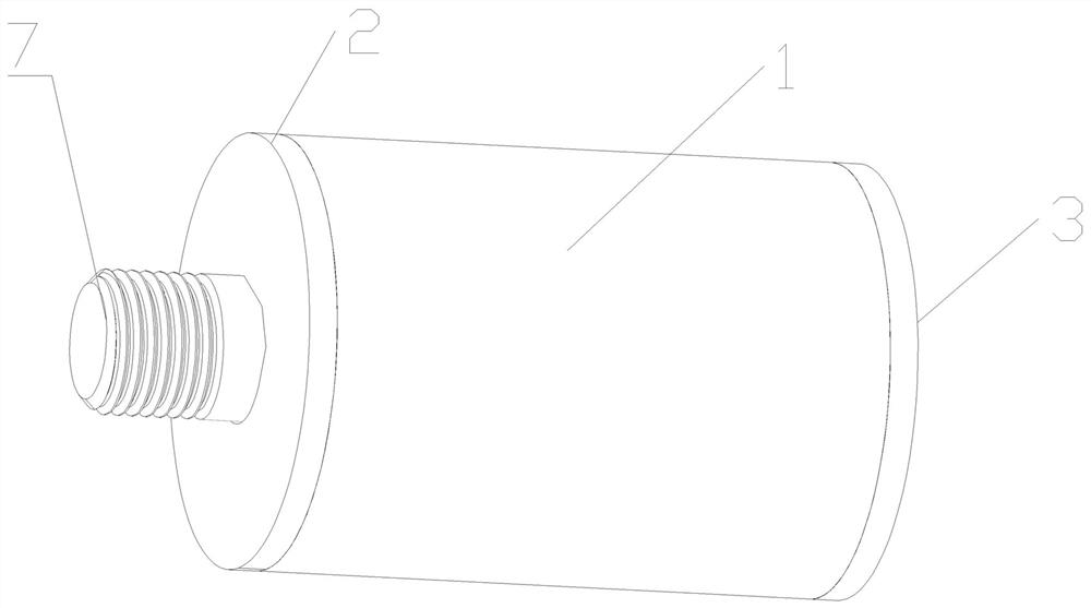
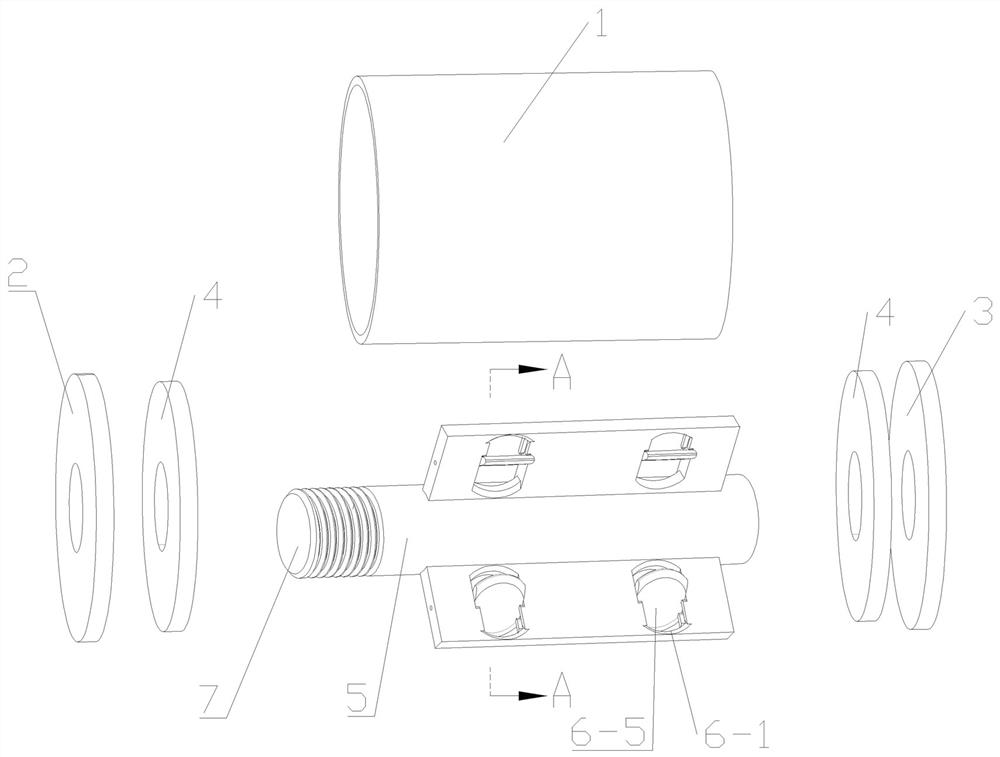
[0037] Such as figure 1 and figure 2 As shown in , the damping hinge of this embodiment includes a cylindrical housing in which a damping shaft 5 is provided and filled with damping fluid. The housing includes a housing 1 and a front end cover 2 and a rear end cover respectively located on the front and rear sides of the housing 1 3. The shell 1 and the rear end cover 3 are an integral structure. The front end cover 2 is welded to the shell 1, or it can be connected by thread or buckle. The front and rear ends of 5 are sleeved with oil-separating rings 4, the inner rings of the front and rear oil-separating rings 4 are interference fit with the damping shaft 5, and the front and rear ends of the damping shaft 5 are rotatable after passing through the oil-separating rings 4 respectively. Connected to the connecting holes on the front end cover 2 and the rear end cover 3, the outer ring of the oil separator 4 is in interference fit with the casing 1, the damping fluid in the c...
Embodiment 2
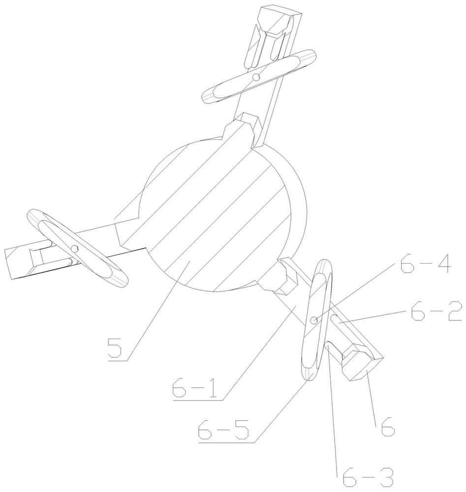
[0047] Such as Figure 4 As shown in , the difference between the damping hinge in this embodiment and Embodiment 1 is that the two strip structures with different lengths on the damping valve 6-1 are respectively located on the front and rear sides of the damping valve 6-1, and both are located at The side opposite to the damping shaft 5 of the hinge pin 6-4. One side of the vane 6-5 is opposite to the two strip structures, and is also opposite to the damping shaft 5, and this side of the vane 6-5 is set as an abutment surface.
[0048] The longer strip structure provided on the damping valve 6-1, one end is connected with the inner side wall of the damping valve 6-1, and the other end is set as the first limiting structure 6-2, and the first limiting structure 6-2 is connected with the blade The abutting surface of 6-5 is opposite, and the first limiting structure 6-2 is used to interfere with the abutting surface of the blade 6-5 when the blade 6-5 rotates to the first lim...
Embodiment 3
[0054] Such as Figure 5 As shown in , the difference between the damping hinge in this embodiment and Embodiment 1 and Embodiment 2 is that there are two protrusions on one side (front side or rear side) of the damping valve 6-1, respectively for the first limit Position structure 6-2 and second position-limiting structure 6-3, the two sides of blade 6-5 are opposite to first position-limiting structure 6-2 and second position-limiting structure 6-3 respectively, and these two sides are respectively The abutting surface of the first gear position and the abutting surface of the second gear position, the distance between the first limiting structure 6-2 and the hinge pin 6-4 is smaller than the distance between the second limiting structure 6-3 and the hinge pin 6-4 distance between.
[0055] When the blade 6-5 rotates towards the first limiting structure 6-2, the first limiting structure 6-2 collides with the abutting surface of the first gear of the blade 6-5, so that the b...
PUM
 Abstract
Description
Claims
Application Information
 - R&D Engineer
- R&D Manager
- IP Professional
- Industry Leading Data Capabilities
- Powerful AI technology
- Patent DNA Extraction
Browse by: Latest US Patents, China's latest patents, Technical Efficacy Thesaurus, Application Domain, Technology Topic, Popular Technical Reports.
© 2024 PatSnap. All rights reserved.Legal|Privacy policy|Modern Slavery Act Transparency Statement|Sitemap|About US| Contact US: help@patsnap.com