
Cutter polishing and cleaning equipment

A technology for cleaning equipment and knives, which is applied to grinding/polishing equipment, metal processing equipment, and other manufacturing equipment/tools, etc. It can solve problems such as safety risks, and achieve the effect of improving safety and improving the wind effect

Active Publication Date: 2022-03-08
重庆市大足区光头刀具有限公司
View PDF5 Cites 0 Cited by
  • Summary
  • Abstract
  • Description
  • Claims
  • Application Information

AI Technical Summary

Problems solved by technology

[0004] The object of the present invention is to provide a tool polishing and cleaning equipment to solve the problem that the tool polishing and cleaning equipment in the prior art has safety risks

Method used


Image

  • Cutter polishing and cleaning equipment
  • Cutter polishing and cleaning equipment
  • Cutter polishing and cleaning equipment

Examples


Embodiment Construction

[0026] Embodiments of the present invention are described in detail below, examples of which are shown in the drawings, wherein the same or similar reference numerals designate the same or similar elements or elements having the same or similar functions throughout. The embodiments described below by referring to the figures are exemplary and are intended to explain the present invention and should not be construed as limiting the present invention.

[0027] In describing the present invention, it should be understood that the terms "length", "width", "upper", "lower", "front", "rear", "left", "right", "vertical", The orientation or positional relationship indicated by "horizontal", "top", "bottom", "inner", "outer", etc. are based on the orientation or positional relationship shown in the drawings, and are only for the convenience of describing the present invention and simplifying the description, rather than Nothing indicating or implying that a referenced device or element...


PUM


Abstract

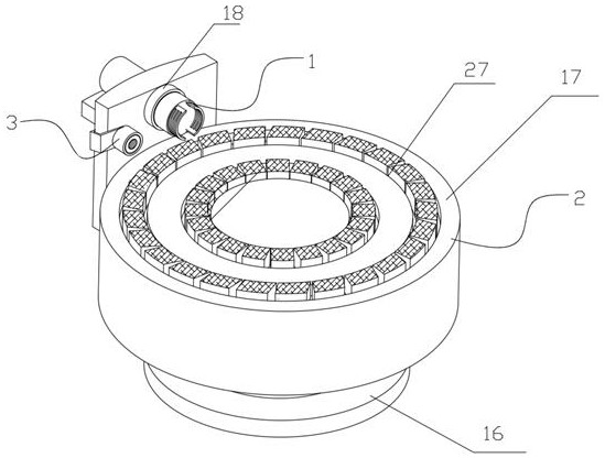
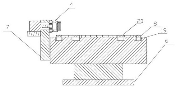
The invention relates to the technical field of intelligent manufacturing equipment, in particular to cutter polishing and cleaning equipment which comprises a cutter clamping seat, a grinding seat and a fan, the cutter clamping seat is arranged on the upper side of the grinding seat and matched with the grinding seat, and the fan is arranged on one side of the grinding seat and matched with the grinding seat; the cutter clamping seat comprises a clamping head and a rotating seat, the rotating seat is arranged on the inner side of the grinding seat, the rotating seat is rotationally matched with the grinding seat, the clamping head is arranged on the upper side of the rotating seat, and the clamping head is fixedly connected with the rotating seat. And therefore, the safety of the cutter polishing process is effectively improved, and the situation that a user is injured is avoided.

Description

technical field [0001] The invention relates to the technical field of intelligent manufacturing equipment, in particular to a tool polishing and cleaning equipment. Background technique [0002] After the tool is used for a long time, due to the wear of the tool, the tool often needs to be polished to improve the service life; [0003] In the prior art, the polishing and cleaning equipment often requires the user to hold the tool in contact with the polishing and cleaning equipment, and use the polishing and cleaning equipment to rub against the tool to achieve polishing. During the use process, it is found that this method has safety risks, and the user is easy to contact with the polishing and cleaning equipment due to hand contact. Injuries caused by polishing and cleaning equipment. Contents of the invention [0004] The object of the present invention is to provide a tool polishing and cleaning device to solve the problem that the tool polishing and cleaning device ...

Claims


Application Information

Patent Timeline
IPC IPC(8): B24B3/00B24B41/06B24B55/06
CPCB24B3/00B24B41/06B24B55/06
Inventor 鄢国红
Owner 重庆市大足区光头刀具有限公司
Learn More