Wear-resistant shaft sleeve structure for sealing speed reducer

A technology for sealing and reducer, applied in the direction of bearing components, shafts and bearings, transmission parts, etc., can solve the problems of pollution, inability to deal with seal failure online, contact wear and so on

Pending Publication Date: 2022-03-04
新疆德勤互力工业技术有限公司
View PDF8 Cites 0 Cited by
  • Summary
  • Abstract
  • Description
  • Claims
  • Application Information

AI Technical Summary

Problems solved by technology

[0002] Generally, the input, output and through cover of the reducer adopt the sealing structure such as skeleton oil seal and sealing felt seal, and the seals are in direct contact with the high-speed input and low-speed output shafts. If there is no special design requirement, the reducer manufacturer usually Without the design of installing detachable and replaceable shaft sleeves, the contact parts between the input and output shaft of the reducer and the oil seal cannot be repaired after wear and tear, and the sealing effect continues to deteriorate, eventually causing a large amount of oil leakage. After the seal fails, the reducer can only be replaced and repaired as a whole. Increased maintenance costs for spare parts
The main problems are as follows: the high-speed shaft of the reducer rotates at a high speed, and the oil seal and the shaft produce relative rotating contact friction. The friction first causes the wear of the seal, and the second causes the contact wear of the journal of the high-speed shaft. As the degree of wear continues to increase, The contact pressure between the skeleton oil seal lip and the journal decreases, resulting in poor sealing effect. Since the journal of the high-speed shaft and the oil seal are designed in direct contact, the problem of seal failure cannot be dealt with online, resulting in more and more serious oil leakage, which eventually leads to lubrication. Equipment lubrication accidents and environmental pollution accidents caused by failure

Method used


Image

  • Wear-resistant shaft sleeve structure for sealing speed reducer

Examples


Embodiment Construction

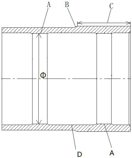
[0008] A wear-resistant ax sleeve for a reductionler seal, such as figure 1 As shown, including a bushing body, the outer peripheral diameter of the outer peripheral edge of the outer peripheral edge of the shaft body is 4 mm than the outer peripheral edge of the right side of the shaft body, and the outer peripheral length C of the right side of the shaft body is 70-90 mm, the right The quenching depth of the side is 1-1.5mm; the middle of the outer peripheral edge of the shaft body has an annular shoulder transition surface B, the left side of the shaft body, and the left side of the shaft body have a shrinking hole A, which two shrinkage holes. The pore size is φ120 mm, the upper deviation + 0.055mm, the lower deviation + 0.025mm is an overference fitting section, the width of the two shrinkles is 20mm, and the bushing between the two shrinkles has a depth of 0.5. The annular machining of the mm D, which has a width of 70-90 mm.


PUM


Abstract

The wear-resistant shaft sleeve structure comprises a shaft sleeve body, the diameter of the outer periphery of the left side portion of the shaft sleeve body is 4 mm smaller than that of the outer periphery of the right side portion of the shaft sleeve body, the length C of the outer periphery of the right side portion of the shaft sleeve body is 70-90 mm, and the quenching depth of the right side portion is 1-1.5 mm; an annular shoulder transition face B is arranged in the middle of the outer periphery of the shaft sleeve body, the left side and the right side of the shaft sleeve body are each internally provided with a necking hole A, the diameter phi of the two necking holes is 120 mm, the upper deviation + 0.055 mm and the lower deviation + 0.025 mm are interference fit sections, the width of the two necking holes is 20 mm, and the diameter phi of the two necking holes is 20 mm. And a section of annular machining cutter groove D with the depth of 0.5 mm is formed in the shaft sleeve body between the two necking holes, and the width of the annular machining cutter groove D is 70-90 mm.

Description

Technical field [0001] The present invention relates to a wear-resistant ax sleeve structure for a reduction in a gear. Background technique [0002] Usually the speed reducer input, the output and the passage portion uses a sealing structure such as a skeleton oil seal, sealing the oil felt seal, and the seal and the high-speed input and low-speed output shaft are directly in contact. If there is no special design requirements, the reducer manufacturing manufacturer usually Do not use the installed detachable replacement sleeve design, the receiver input and output shaft and the oil seal cannot be repaired after wear, the sealing effect continues to deteriorate, and finally cause a large amount of leakage, and the sealing failure will only replace the maintenance. There is increased maintenance cost of spare parts. The main problems are as follows: The speed rotation high speed axis is rotated, the oil seal is generated relative to the axis, and the friction is caused by the wea...

Claims


Application Information

Patent Timeline
Patent Type & Authority Applications(China)
IPC IPC(8): F16H57/029F16H57/021F16C33/04
CPCF16H57/029F16H57/021F16C33/04
Inventor 李红熙蒋文忠
Owner 新疆德勤互力工业技术有限公司
Why Eureka
Try Eureka