
Shell assembly, compressor and air conditioner

A shell assembly and compressor technology, which is applied in the field of compressors, can solve problems such as failure to make timely protection actions, weak installation structure of temperature sensors, and temperature data distortion.

Pending Publication Date: 2022-03-04
GUANGDONG MEIZHI PRECISION MFG +1
View PDF0 Cites 0 Cited by
  • Summary
  • Abstract
  • Description
  • Claims
  • Application Information

AI Technical Summary

Problems solved by technology

[0003] In the related art, the outdoor unit of some air conditioners is provided with a temperature sensor on the compressor, but the installation structure of the temperature sensor is not firm, and the temperature sensor is easy to loosen, so the detected temperature data is distorted. The temperature data of the compressor is used to control the compressor, and the protection action may not be taken in time, resulting in the failure of the compressor such as pump body wear and motor demagnetization

Method used


Image

  • Shell assembly, compressor and air conditioner
  • Shell assembly, compressor and air conditioner
  • Shell assembly, compressor and air conditioner

Examples


Embodiment Construction

[0035] Embodiments of the present invention are described in detail below, examples of which are shown in the drawings, wherein the same or similar reference numerals designate the same or similar elements or elements having the same or similar functions throughout. The embodiments described below by referring to the figures are exemplary only for explaining the present invention and should not be construed as limiting the present invention.

[0036] In the description of the present invention, it should be understood that the orientation descriptions, such as up, down, front, back, left, right, etc. indicated orientations or positional relationships are based on the orientations or positional relationships shown in the drawings, and are only In order to facilitate the description of the present invention and simplify the description, it does not indicate or imply that the device or element referred to must have a specific orientation, be constructed and operated in a specific ...


PUM


Abstract

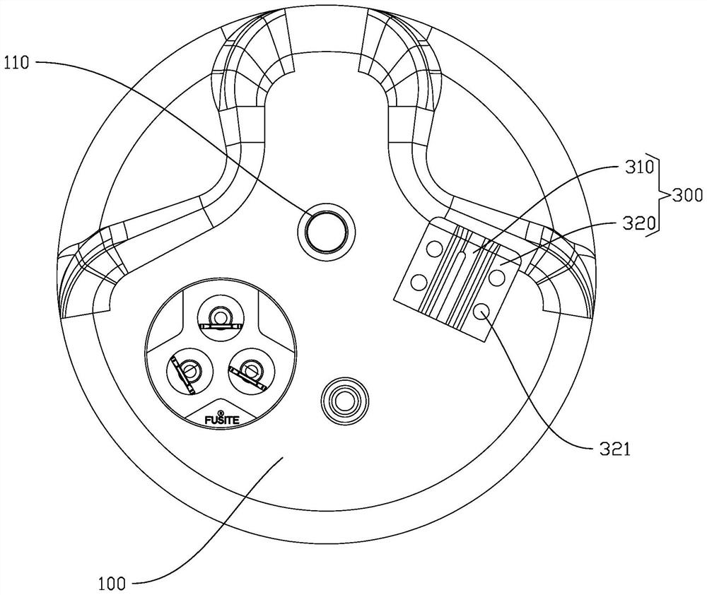
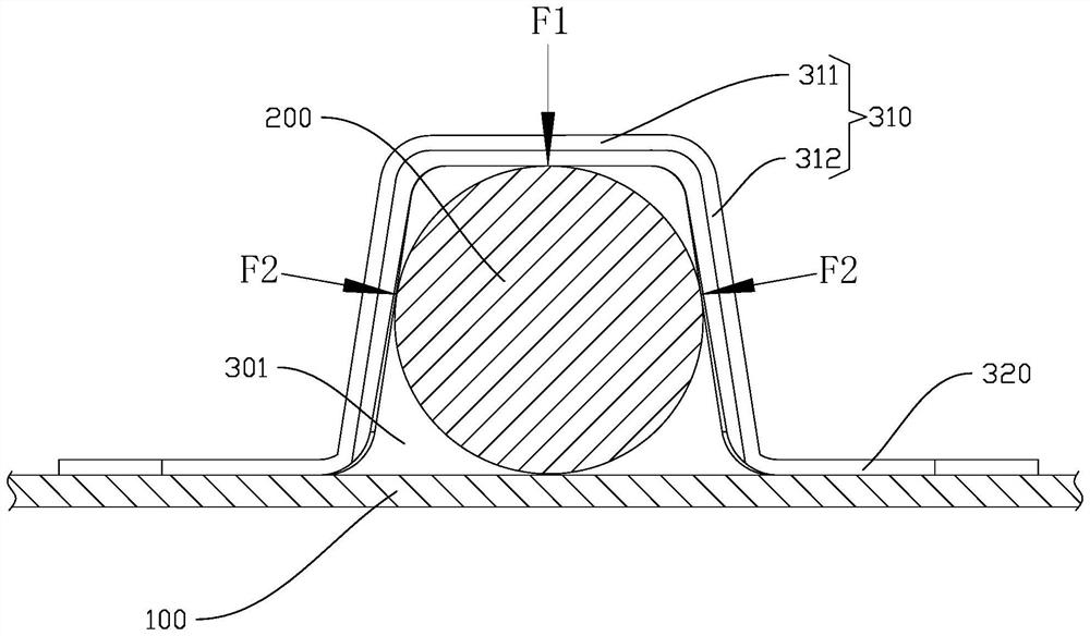
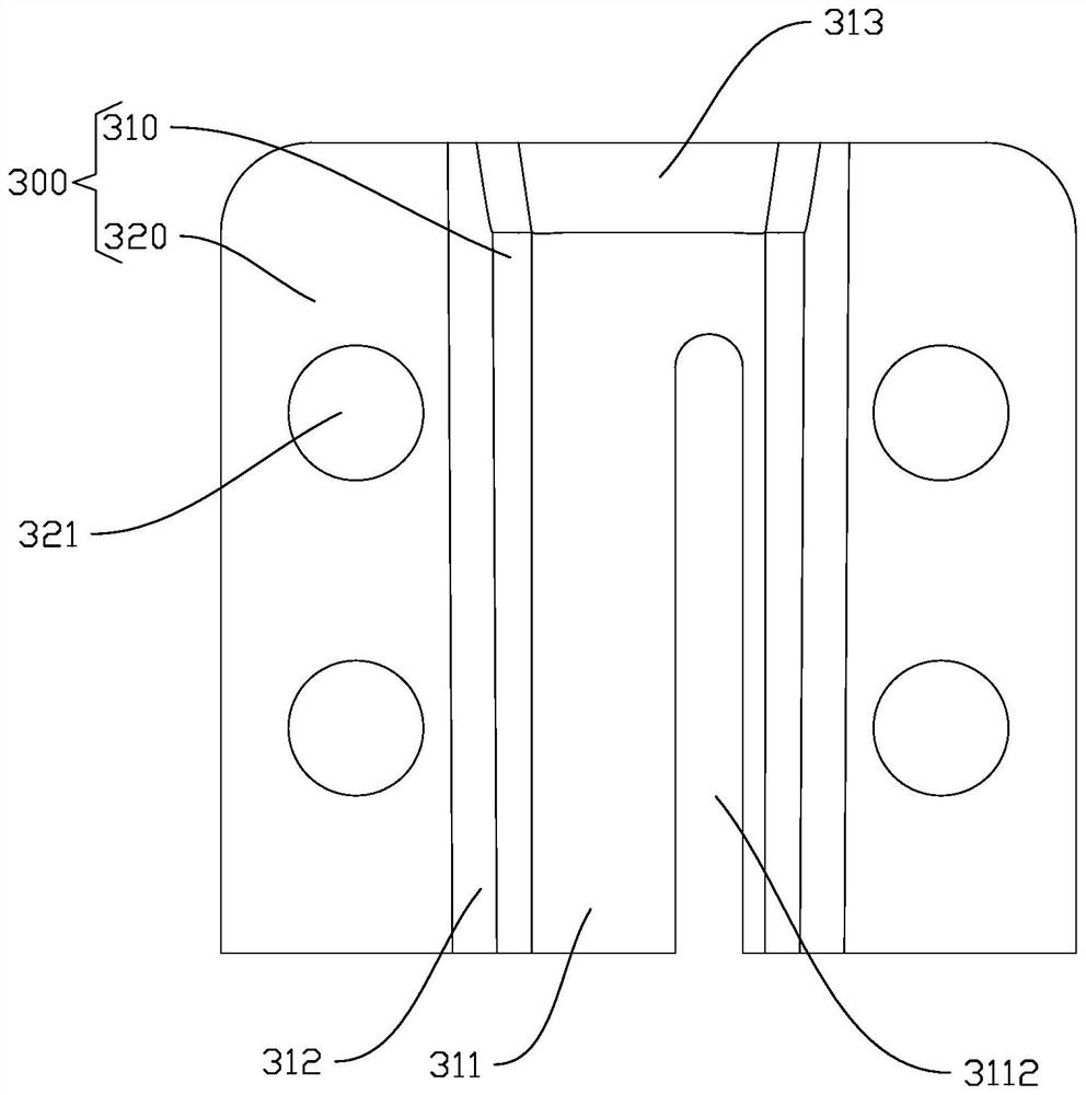
The shell assembly comprises a shell, a temperature sensor and a fixing support, the temperature sensor abuts against the outer wall of the shell, the fixing support comprises a fixing part and connecting parts located on the two sides of the fixing part, the connecting parts are fixedly connected to the shell, and a mounting cavity is formed between the fixing part and the shell; the fixing part is provided with an inlet end for the temperature sensor to be installed in the installation cavity and comprises a top plate and two side plates connected to the two sides of the top plate, the included angle between the top plate and the side plates is an obtuse angle, the top plate is provided with an open groove deviating from the inlet end, and the open groove deviates from the center line of the top plate. A top plate and two side plates of the fixing part are distributed in a trapezoid shape, the top plate abuts against the temperature sensor from the top, the side plates on the two sides apply pressure to the temperature sensor from the two sides, and the top plate is provided with an opening groove to increase elasticity, so that the top plate presses the temperature sensor, and the temperature sensor keeps making contact with the outer wall of the shell.

Description

technical field [0001] The invention relates to the technical field of compressors, in particular to a shell assembly, a compressor and an air conditioner. Background technique [0002] The compressor is an important part of the air conditioner, and the compressor plays the role of compressing and driving the refrigerant in the refrigerant circuit. The compressor is generally installed inside the outdoor unit of the air conditioner. The compressor extracts and compresses the refrigerant from the low-pressure area, and then sends it to the condenser, which dissipates heat through the condenser to make the refrigerant change from gas to liquid. [0003] In the related art, the outdoor unit of some air conditioners is provided with a temperature sensor on the compressor, but the installation structure of the temperature sensor is not firm, and the temperature sensor is easy to loosen, so the detected temperature data is distorted. The temperature data of the compressor is used...

Claims


Application Information

Patent Timeline
IPC IPC(8): F04B39/12F04B39/14F04B51/00G01K1/14
CPCF04B39/121F04B39/14F04B51/00G01K1/14
Inventor 王毅强樊峰刚
Owner GUANGDONG MEIZHI PRECISION MFG
Learn More