Transmission of mini-tiller

A transmission and micro-tiller technology, which is applied in agricultural machinery, agricultural machinery and implements, agriculture, etc., can solve the problems of high height of the micro-tiller, and achieve the effects of improving light weight, facilitating lubrication, and improving miniaturization.

Active Publication Date: 2022-03-04
CHONGQING HWASDAN AGRI EQUIP MFG CO LTD
View PDF9 Cites 0 Cited by
  • Summary
  • Abstract
  • Description
  • Claims
  • Application Information

AI Technical Summary

Problems solved by technology

[0005] The present invention intends to provide a micro-tiller transmission to solve the problem in the prior art that the height of the micro-tiller is too high to perform mechanically automated agricultural operations in the space under the crops with low leaves

Method used


Image

  • Transmission of mini-tiller
  • Transmission of mini-tiller
  • Transmission of mini-tiller

Examples


Embodiment

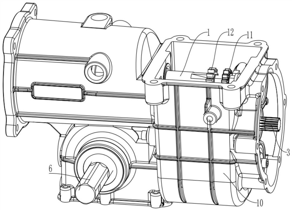
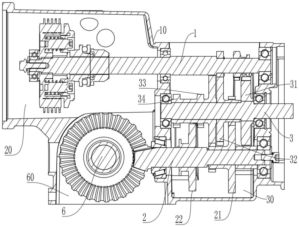
[0038] The embodiment is basically as attached figure 1 As shown, the tiller transmission includes a casing 10 and a transmission system located in the casing 10. The casing 10 includes a clutch chamber 20, a speed change chamber 30 and a travel chamber 60 that communicate with each other. The clutch chamber 20 and the travel chamber 60 are located at On the same side of the transmission chamber 30, the clutch chamber 20 is used to accommodate the clutch, and the transmission chamber 30 is used to accommodate transmission parts of the transmission system.

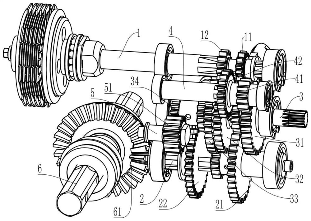
[0039] The transmission system includes the main shaft 1, the travel output shaft 2, the tool output shaft 3, the intermediate shaft 4 and the reverse gear shaft 5 that are rotatably connected to the chamber wall of the transmission chamber 30. The main shaft 1 is axially slidably connected with a shift gear 11, and the tool output A fixed gear 31 is fixedly connected to the shaft 3, and a transition gear set is set on the ...


PUM


Abstract

The invention relates to the technical field of agricultural machinery, and particularly discloses a mini-tiller speed changer which comprises a box body and a transmission system located in the box body, the transmission system comprises a main shaft, a walking output shaft and a cutter output shaft, speed changing cavities communicated with one another are formed in the box body, a walking cavity is further formed in the box body, and the walking cavity is communicated with the speed changing cavities; the main shaft, the walking output shaft and the cutter output shaft are all rotationally connected to the cavity wall of the speed changing cavity, and the cavity wall of the walking cavity is rotationally connected with a walking shaft. A transmission gear is arranged between the walking shaft and the walking output shaft and located in the walking cavity. According to the scheme, the problem that in the prior art, a mini-tiller is large in height and cannot conduct mechanical automatic agricultural operation in the space below crops with low leaves is solved.

Description

technical field [0001] The invention relates to the technical field of agricultural machinery, in particular to a micro tiller transmission. Background technique [0002] In the current agricultural machinery, micro tillage machines are often used to ditch, cultivate soil and rotary tillage on the land. Due to different methods, the rotation direction and speed of the cutter are different. For example, the rotation direction of the cutter is different when ditching and rotary tillage They are not the same, and the tool speeds required for ditching and rotary tillage are also different, resulting in the subdivision of micro-tillers in existing agricultural operations into micro-tillers for ditching and soil cultivation and micro-tillers for rotary tillage. This will undoubtedly increase the cost of equipment for agricultural operations, and when both rotary tillage and ditching after rotary tillage are required on the same day, the operator has to spend time and manpower to p...

Claims


Application Information

Patent Timeline
Patent Type & Authority Applications(China)
IPC IPC(8): A01B71/06
CPCA01B71/06
Inventor 鲜鹏刘大明李想李鑫熊卓宇苏德超
Owner CHONGQING HWASDAN AGRI EQUIP MFG CO LTD
Why Eureka
Try Eureka