
Adjusting support of surge shaft fast door laser range finder and manufacturing method

A technology of laser rangefinder and bracket adjustment, which is applied in the direction of machine platform/bracket, support machine, final product manufacturing, etc. It can solve the problems of inconvenient angle adjustment, achieve rapid and accurate angle adjustment, and quickly and accurately measure the opening of fast doors , the effect of improving work efficiency

Pending Publication Date: 2022-03-01
STATE GRID HEILONGJIANG ELECTRIC POWER COMPANY +1
View PDF0 Cites 0 Cited by
  • Summary
  • Abstract
  • Description
  • Claims
  • Application Information

AI Technical Summary

Problems solved by technology

[0004] The object of the present invention is to provide an adjustment bracket and a manufacturing method for the laser range finder of the fast door of the surge shaft. The problem of inconvenient angle adjustment during installation

Method used


Image

  • Adjusting support of surge shaft fast door laser range finder and manufacturing method
  • Adjusting support of surge shaft fast door laser range finder and manufacturing method
  • Adjusting support of surge shaft fast door laser range finder and manufacturing method

Examples


Embodiment 1

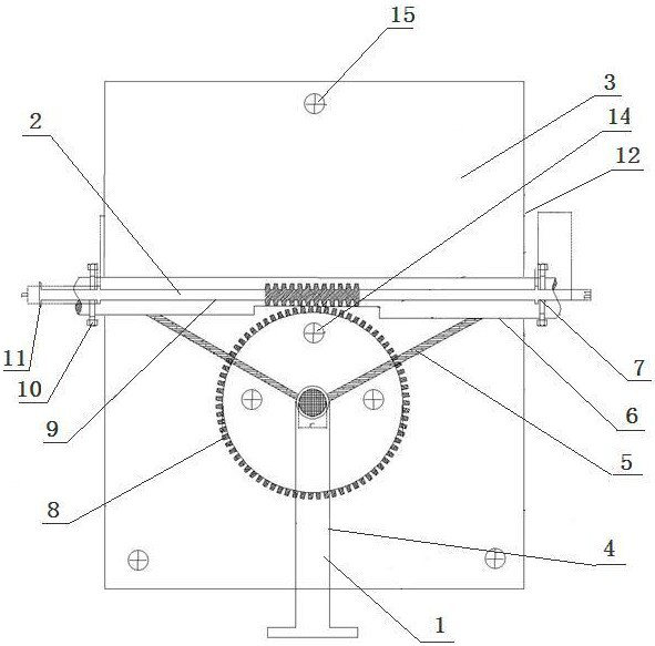
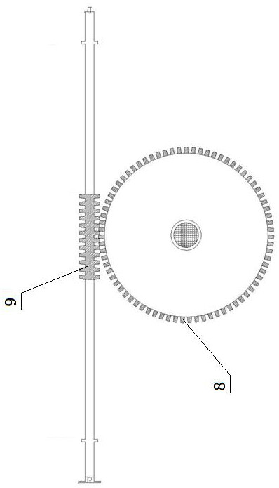
[0035] An adjustment bracket of a laser rangefinder for a fast door of a surge well, which consists of: a fixed bracket 1, an adjustment transmission mechanism 2, and a rangefinder fixing plate 3, the fixed bracket includes a bracket crank arm 4, and the The bottom of the bracket crank arm is connected to the base, the top of the bracket crank arm is connected to the sleeve 6 through the triangle bracket 5, the bottom of the sleeve has a rectangular opening, and the adjustment transmission mechanism includes a worm wheel 8. The worm wheel and the worm 9 are engaged in the rectangular opening, the worm is fixed in the sleeve, and are limited by stop screws 10 at both ends, and the worm wheel is installed on the bracket corner on the arm and fixed with the fixed plate by bolts.

Embodiment 2

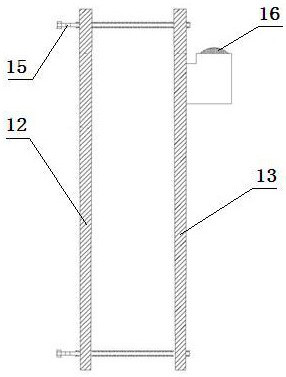
[0037] According to the adjustment bracket of the laser rangefinder of the fast door of the surge shaft described in Embodiment 1, the fixed plate of the rangefinder includes an inner plate 12, and the inner plate passes through the worm wheel and the bracket The crank arm is connected, the inner layer board is connected with the outer layer board 13 through three adjusting screws 15, the side wall of the outer layer board is equipped with a bubble level 16, and the inner layer board is connected with three follower screws 14 Connected with the bracket arm, the two ends of the worm are equipped with operating handles 11 .

Embodiment 3

[0039] According to the adjustment bracket of the laser rangefinder for the fast door of the surge shaft described in Embodiment 1, there are four limit holes 7 on both sides of the sleeve for installing the limit screws, and the bracket arm There is a 60° inclination angle structure between the tripod and the tripod.


PUM


Abstract

The invention discloses a surge shaft fast door laser range finder adjusting support and a manufacturing method. In the prior art, when a hydraulic power plant surge shaft rapid door laser range finder is installed, the angle is difficult to adjust rapidly and accurately to measure the opening degree of the rapid door. The device comprises a fixed bracket (1), an adjusting transmission mechanism (2) and a range finder fixing plate (3), the fixed bracket comprises a bracket crank arm (4), the bottom of the bracket crank arm is connected with a base, the top of the bracket crank arm is connected with a sleeve (6) through a triangular support (5), the bottom of the sleeve is provided with a rectangular opening, the adjusting transmission mechanism comprises a worm gear (8), and the worm gear (8) is connected with the base. The worm gear and a worm (9) are meshed in the rectangular opening, the worm is fixed in the sleeve, the two ends of the worm are limited through limiting screws (10), and the worm gear is installed on the bracket crank arm and fixed to the fixing plate through bolts. The laser range finder adjusting support is used for the surge shaft fast door.

Description

technical field [0001] The invention relates to the technical field of laser tools, in particular to an adjustment bracket and a manufacturing method of a laser range finder for a fast door of a surge well. Background technique [0002] The quick door of the surge shaft of a hydropower plant is a water barrier gate located between the water inlet of the hydroelectric unit and the guide vane of the volute. important role; [0003] The fast door laser rangefinder is installed above the fast door to provide the control unit with a sensor for the real-time opening of the fast door. The laser rangefinder measures the reflection of the laser beam by shooting the laser at the disc fixed on the hydraulic boom of the fast door. The opening of the fast door is calculated by returning the time of the range finder. In order to ensure that the laser can always accurately shoot to the center of the disc and reflect when the disc moves up and down with the fast door, there are strict requ...

Claims


Application Information

Patent Timeline
IPC IPC(8): F03B11/00F16M11/12F16M11/18
CPCF03B11/008F16M11/12F16M11/18B23P15/00Y02E10/20Y02P70/50
Inventor 杨焱强李晓堂洪吉龙许松娜李兴宇
Owner STATE GRID HEILONGJIANG ELECTRIC POWER COMPANY
Learn More