
Marine three-section folding vehicle springboard structure

A technology for vehicle springboards and springboards, applied in ship accessories, passenger handling equipment, ships, etc., can solve problems that affect the realization of the original function, affect the use of other decks, affect the appearance, etc., and achieve the effect of good use safety.

Active Publication Date: 2022-03-01
708TH RES INST OF CSSC
View PDF9 Cites 1 Cited by
  • Summary
  • Abstract
  • Description
  • Claims
  • Application Information

AI Technical Summary

Problems solved by technology

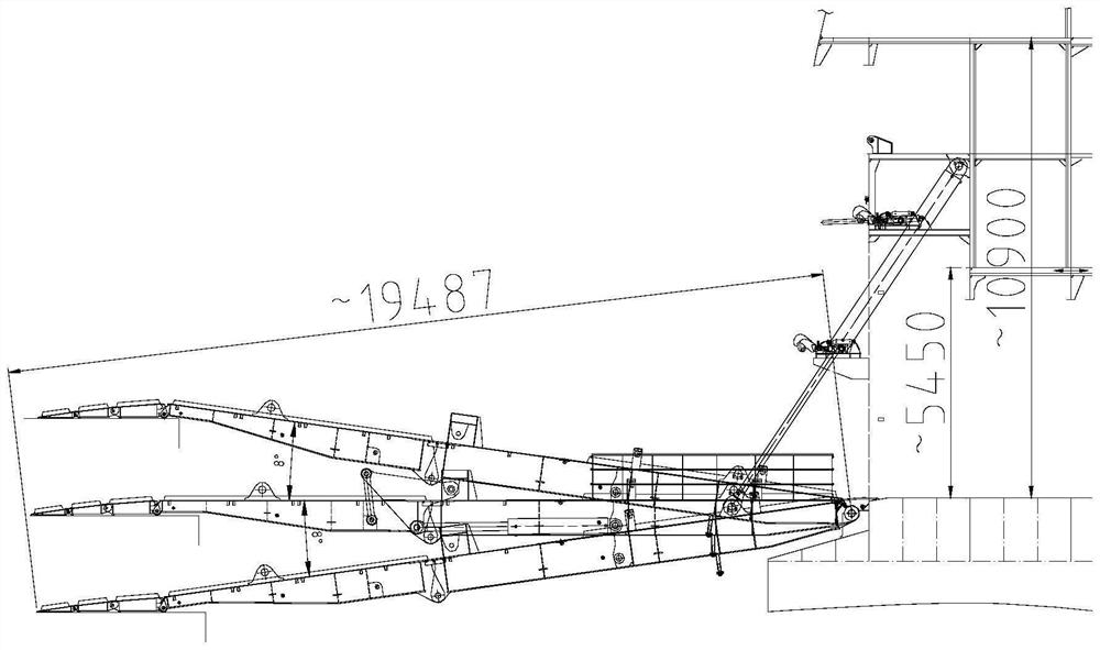
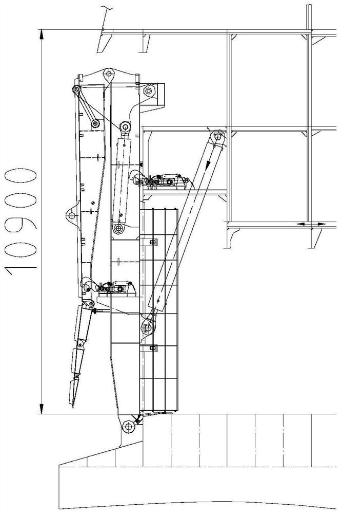
[0003] The current vehicle springboard is mostly one section of springboard plus wing board or two sections of springboard plus wing board. When storing, because the length of this section of springboard (or the first section of the two sections of springboard) is longer, the top of the vehicle springboard is much higher than where the vehicle springboard is located. Ro-Ro decks (two decks or even three decks high), affect the use of other decks and affect the appearance, such as attached figure 2 shown
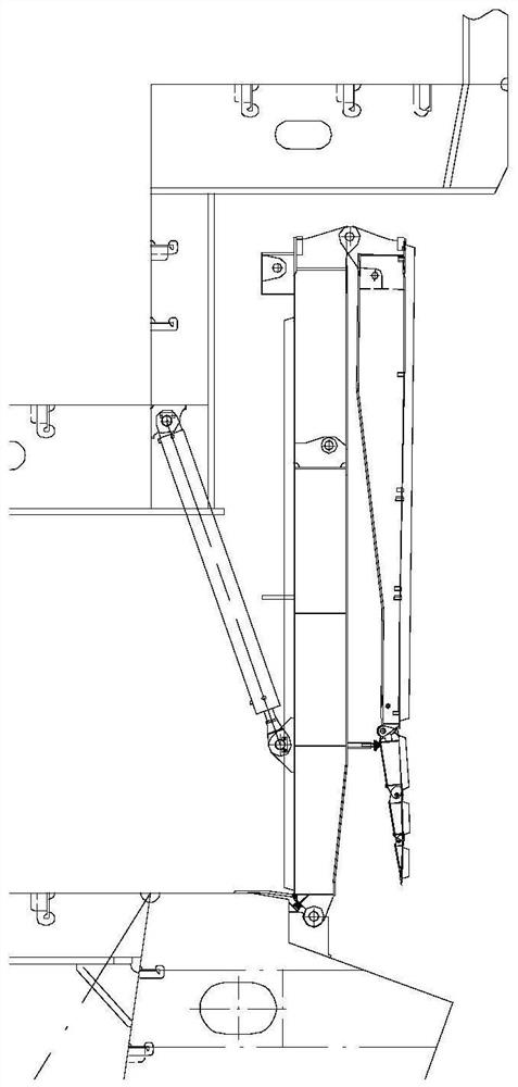
[0004] Especially for ship arrangements with ro-ro spaces (such as multi-purpose ships or research and official ships), it will especially affect the overall arrangement of the ship, such as attached image 3 As shown, the storage vehicle springboard can only partially raise the top deck, but since the top deck has its original functions (such as laboratories, equipment workshops, etc.), local elevation will affect the realization of the original functions

Method used


Image

  • Marine three-section folding vehicle springboard structure
  • Marine three-section folding vehicle springboard structure
  • Marine three-section folding vehicle springboard structure

Examples


Embodiment Construction

[0036] The present invention will be further described below in conjunction with the accompanying drawings and specific embodiments, but not as a limitation of the present invention.

[0037] See Figure 4 to Figure 7 As shown, in the embodiment of the present invention, a marine three-section folding vehicle springboard structure is shown, including: top deck 01, roll-off deck 02, hull member 03, first section springboard 11, second section springboard 12, first section springboard 12, Three-section springboard 13, one-section wing plate 14, connection mechanism one 15, connection mechanism two 16, connection mechanism three 17, steel baffle plate 18, wire rope winch 21, second support wire rope 22, first support cylinder 23, connection mechanism Four 24, wharf plane 31.

[0038] The ro-ro deck 02 is fixedly connected with the hull member 03, the top of the hull member 03 is fixedly connected with the top deck 01, the bottom surface of the top deck 01 is equipped with a fixe...


PUM


Abstract

The invention relates to a marine three-section folding vehicle springboard structure, which relates to the technical field of marine vehicle springboards, and comprises a first section of springboard, a second section of springboard, a third section of springboard and a first section of wing plate which are sequentially connected from a roll-on-roll-off deck, rotatable connecting devices are arranged between the roll-on-roll-off deck and the first section of springboard, between the first section of springboard and the second section of springboard, between the second section of springboard and the third section of springboard, and between the third section of springboard and the first section of wing plate. A locking device is additionally arranged between the first section of springboard and the second section of springboard and / or between the second section of springboard and the third section of springboard; when the first section of springboard is folded upwards relative to the roll-on-roll-off deck, the second section of springboard is folded downwards on the lower surface of the first section of springboard, the third section of springboard is folded upwards on the upper surface of the second section of springboard, and the first section of wing plate is folded downwards on the lower surface of the third section of springboard. The use of other layers of decks cannot be affected, the overall arrangement of a ship is guaranteed, and meanwhile better use safety of the vehicle gangplank is guaranteed.

Description

technical field [0001] The invention relates to the technical field of a marine vehicle springboard, in particular to a marine three-section folding vehicle springboard structure. Background technique [0002] For the ro-ro space of the ship, in order to facilitate the entry and exit of ro-ro vehicles, a vehicle springboard is often provided as a set. Since the height difference between the ro-ro deck where the vehicle springboard is located and the wharf plane is a variable, and the downward use angle of the vehicle springboard is generally between 8 and 11 degrees at most, this makes the length of the vehicle springboard often relatively long, such as attached figure 1 shown. [0003] The current vehicle springboard is mostly one section of springboard plus wing board or two sections of springboard plus wing board. When storing, because the length of this section of springboard (or the first section of the two sections of springboard) is longer, the top of the vehicle sp...

Claims


Application Information

Patent Timeline
Patent Type & Authority Applications(China)
IPC IPC(8): B63B27/14
CPCB63B27/143B63B2027/141Y02T70/10
Inventor 吴彬黄维张海瑛贺卫东何夏茵汤霄扬俞赟欧阳梅花
Owner 708TH RES INST OF CSSC
Learn More