
Drilling and threading binding machine

A binding machine and drilling mechanism technology, applied in binding, metal processing, etc., can solve the problems of poor binding effect, low degree of automation, cumbersome operation, etc., and achieve the effects of shortening binding time, improving binding efficiency, and simple structure

Pending Publication Date: 2022-03-01
ZHONGCHAUNGEN TIANJIN TECH CO LTD
View PDF0 Cites 1 Cited by
  • Summary
  • Abstract
  • Description
  • Claims
  • Application Information

AI Technical Summary

Problems solved by technology

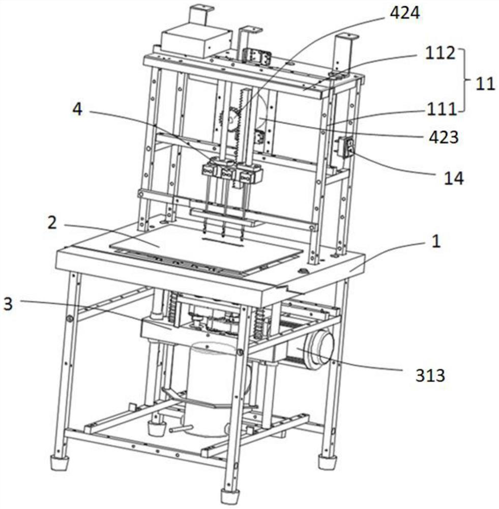
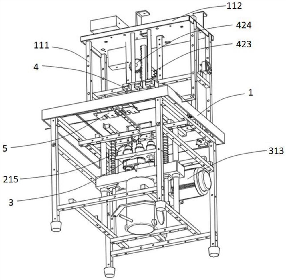
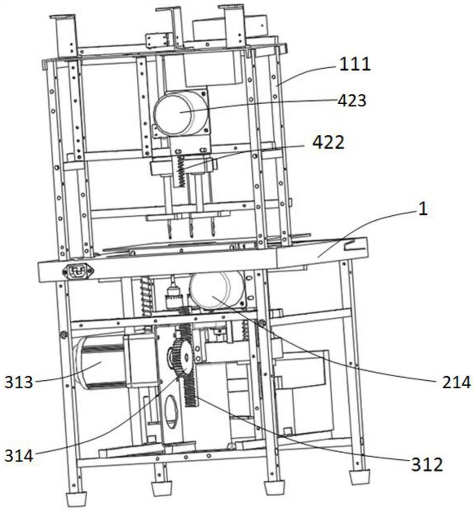
[0003] In order to solve the above problems, the object of the present invention is to provide a drilling and threading binding machine, which solves the problems of complex structure, cumbersome operation, low degree of automation, poor binding effect and low efficiency in the prior art.

Method used


Image

  • Drilling and threading binding machine
  • Drilling and threading binding machine
  • Drilling and threading binding machine

Examples


Embodiment Construction

[0034] In order to make the object, technical solution and advantages of the present invention clearer, the present invention will be further described in detail below in conjunction with the accompanying drawings and embodiments. It should be understood that the specific embodiments described here are only used to explain the present invention, not to limit the present invention.

[0035] In the description of the present invention, it needs to be clarified that the terms "vertical", "transverse", "longitudinal", "front", "rear", "left", "right", "upper", "lower", " "Horizontal" and other indication orientations or positional relationships are based on the orientations or positional relationships shown in the drawings, which are only for the convenience of describing the present invention, and do not mean that the devices or components referred to must have specific orientations or positions, so they cannot be understood as Limitations on the Invention.

[0036] In the descrip...


PUM


Abstract

The drilling and threading binding machine comprises a rack assembly, a drilling mechanism, a threading mechanism, a thread supply mechanism and a top plate mechanism, wherein the drilling mechanism, the threading mechanism, the thread supply mechanism and the top plate mechanism are arranged on the rack assembly; the drilling mechanism drives the top plate mechanism to move and press the to-be-bound object, the drilling mechanism drills the pressed to-be-bound object, and the drilling mechanism automatically resets; the threading mechanism drives the thread supply mechanism to move to the side, away from the threading mechanism, of the top plate mechanism, and the threading mechanism penetrates through the top plate mechanism to hook the binding thread arranged on the thread supply mechanism to conduct threading binding on the drilled to-be-bound object. By means of the drilling and threading binding machine of the structure, the purpose of fully automatically completing drilling and threading is achieved, the time for binding objects to be bound is effectively shortened, and then the binding efficiency is improved; in addition, the drilling and threading binding machine is simple in structure, easy to operate and worthy of being vigorously popularized and used.

Description

technical field [0001] The invention belongs to the technical field of thread binding, in particular to a drilling thread binding machine. Background technique [0002] Existing bookbinding machine generally punches out binding hole earlier with paper when carrying out work, and then binding ring is pressed in the binding hole of paper, completes binding. Mostly at present when binding, put into the punching machine after the paper that needs binding is stacked manually, after punching is finished, manually stack the paper and put it into the binding machine for binding. Such a production method has a large amount of manual labor, low degree of automation, and low production efficiency. For this reason, an integrated punching and binding machine that pushes paper blocks between the punching machine and the binding machine has appeared, and the punching machine and binding have been realized. The transfer of paper between machines reduces the amount of manual labor. However,...

Claims


Application Information

Patent Timeline
IPC IPC(8): B42B2/06B26F1/16
CPCB42B2/06B26F1/16
Inventor 李娟
Owner ZHONGCHAUNGEN TIANJIN TECH CO LTD
Learn More