
An adjustable vibration damping device for a medical bed

A vibration damping device and an adjustable technology, which can be used in hospital beds, medical science, hospital equipment, etc., can solve the problems of inability to adjust the patient's position, secondary injury of the patient, and poor vibration damping effect, so as to improve the ability to withstand gravity and quickly Easy to change bed and operate

Active Publication Date: 2022-05-03
新乡医学院三全学院
View PDF14 Cites 0 Cited by
  • Summary
  • Abstract
  • Description
  • Claims
  • Application Information

AI Technical Summary

Problems solved by technology

The medical bed with wheels is used to transfer patients. The medical bed with wheels will vibrate poorly during the moving project, especially in the process of turning. If the turning speed is too fast, a large lateral force will be generated, which is harmful to the patient. impact, the existing medical bed has poor vibration damping effect, and cannot buffer the lateral force generated by the steering. For patients with fractures who cannot stand, when the patient needs to change the bed, the medical staff usually lift the patient to change the bed. Multiple medical staff are required to operate at the same time, the range is large, and the operation is cumbersome. If the operation is improper, it is easy to cause secondary injury to the patient, and the position of the patient cannot be adjusted. The practicability is poor. The existing medical bed cannot Realizing automatic bed changing for patients cannot meet the needs in actual use, so there is an urgent need for improved technology on the market to solve the above problems

Method used


Image

  • An adjustable vibration damping device for a medical bed
  • An adjustable vibration damping device for a medical bed
  • An adjustable vibration damping device for a medical bed

Examples


Embodiment 1

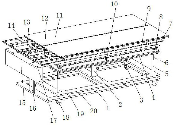
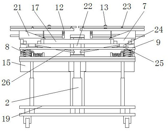
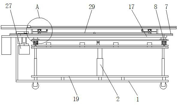
[0028] see Figure 1-9, the present invention provides a technical solution: an adjustable vibration damping device for a medical bed, including a mobile base frame 1, a transverse sliding frame 3, a lifting frame 4, a rotating frame 7, a separated bed frame I12, a separated bed frame II14, and a rotating support The beam 17, the inclined guide mechanism 21, the force bearing arm 29 and the lateral vibration damping mechanism 33, the separated bed frame I12 and the separated bed frame II14 form the bed frame, and the bed frame is provided with a bed board 11, and the separated bed frame I12 and the separated bed frame II14 have the same structure, and the bed board 11 is set in two pieces, the upper surface of the separated bed frame I12 and the upper surface of the separated bed frame II14 are provided with guide rails 23, the bed board 11 is slidingly connected with the separated bed frame through the guide rails 23, the left side of the upper surface of the separated bed fra...


PUM


Abstract

The invention discloses an adjustable vibration damping device for a medical bed, which comprises a movable base frame, a horizontal sliding frame, a lifting frame, a rotating frame, a separated bed frame I, a separated bed frame II, a rotating support beam, an inclined guiding mechanism, a force-bearing The arm and the transverse vibration damping mechanism, the separated bed frame I and the separated bed frame II form a bed frame, and the bed board is arranged on the bed frame, and the separated bed frame I and the separated bed frame II have the same structure, and the force-bearing support arms are set to two, and the force-bearing The support arms are rotatably connected to the lower surface of the separated bed frame I and the separated bed frame II respectively, the rotating frame is located directly below the bed frame, and the upper surface of the rotating frame is provided with an electric telescopic rod III, and the telescopic end of the electric telescopic rod III is connected to the stressed support arm The middle part of the device is connected; the invention has a novel structural design, can adjust the position of the patient, has a good vibration reduction effect, can buffer the lateral force generated during the transfer process, and can realize rapid buffering of the patient at the same time, and is easy to operate.

Description

technical field [0001] The invention relates to the technical field of vibration reduction for medical beds, in particular to an adjustable vibration reduction device for medical beds. Background technique [0002] Medical beds are bed products used in hospitals, nursing homes, community clinics and other places; with the development of technology, people have higher and higher requirements for medical beds. Medical beds can be classified into wheeled medical beds, non- Medical bed with wheels; according to function, it can be divided into operating bed and nursing bed. The medical bed with wheels is used to transfer patients. The medical bed with wheels will vibrate poorly during the moving project, especially in the process of turning. If the turning speed is too fast, a large lateral force will be generated, which is harmful to the patient. impact, the existing medical bed has poor vibration damping effect, and cannot buffer the lateral force generated by the steering. F...

Claims


Application Information

Patent Timeline
Patent Type & Authority Patents(China)
IPC IPC(8): A61G1/02A61G1/04A61G7/10F16F15/08
CPCA61G1/02A61G1/04A61G7/10A61G7/1019A61G7/103A61G7/1036A61G7/1057F16F15/085A61G2203/723
Inventor 吴亦男张文熙毛琳琳宁洁李晓敏
Owner 新乡医学院三全学院
Learn More