
Click test device

A technology of testing device and indenter, which is applied in the direction of measuring device, testing of mechanical parts, testing of machine/structural parts, etc., can solve the problems of high maintenance cost, reduction of connection parts, unstable output pressure, etc.

Active Publication Date: 2022-02-25
BEIJING HONOR DEVICE CO LTD
View PDF11 Cites 0 Cited by
  • Summary
  • Abstract
  • Description
  • Claims
  • Application Information

AI Technical Summary

Problems solved by technology

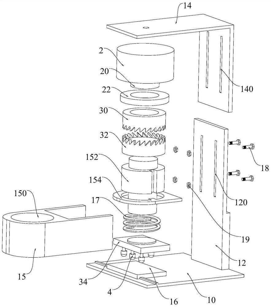
In this structure, the transmission mechanism includes the first part and the second part which are opposed to each other. The first part and the second part are arranged in sequence along the axial direction of the power output shaft, which simplifies the structure of the transmission mechanism, realizes accurate transmission of pressure values, and improves the mechanical efficiency. transmission efficiency, and reduce the connecting parts of the transmission mechanism, so as to ensure the stability and reliability of action transmission, and solve the problems of unstable output pressure and high maintenance cost in the prior art; the first part is fixedly connected to the power output shaft, and the second The parts are slidingly connected to the frame, and the opposite ends of the first part and the second part are arranged in a non-planar structure, and the rotation of the first part is converted into the linear movement of the second part through mutual extrusion between the first part and the second part; The indenter assembly is connected to the second part, and the second part drives the indenter assembly to move back and forth, thereby realizing the clicking action

Method used


Image

  • Click test device
  • Click test device
  • Click test device

Examples


Embodiment Construction

[0061] In order to better understand the technical solutions of the present application, the embodiments of the present application will be described in detail below in conjunction with the accompanying drawings.

[0062] In a specific embodiment, the present application will be further described in detail below through a specific embodiment and in conjunction with the accompanying drawings.

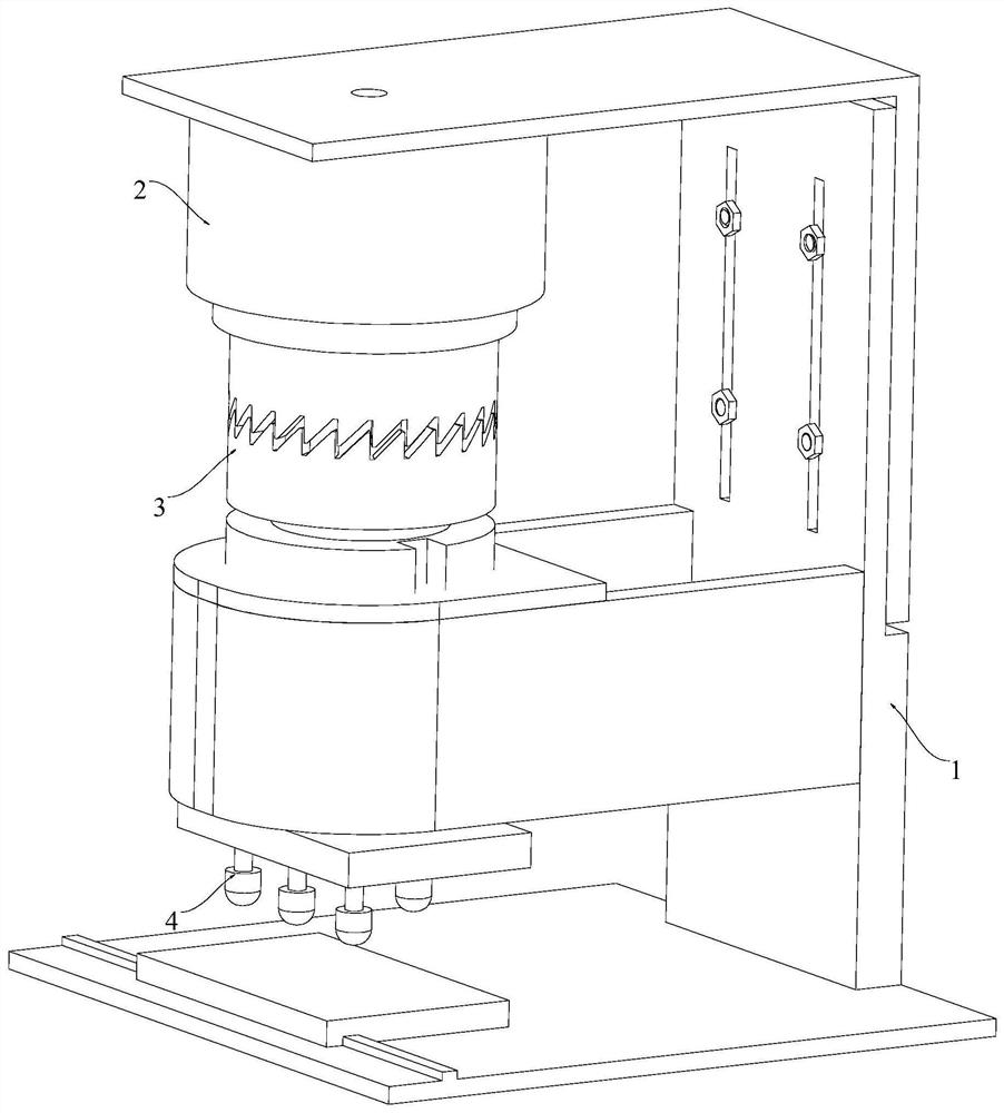
[0063] The embodiment of the present application provides a click test device. The click test device is applied to the touch screen or button of electronic products such as mobile phones, tablet computers or notebooks. The risk of failure under finger pressing or other extrusion scenarios can be detected by the indenter assembly. Squeeze the tested sample to complete the click life test of internal components and external structures.

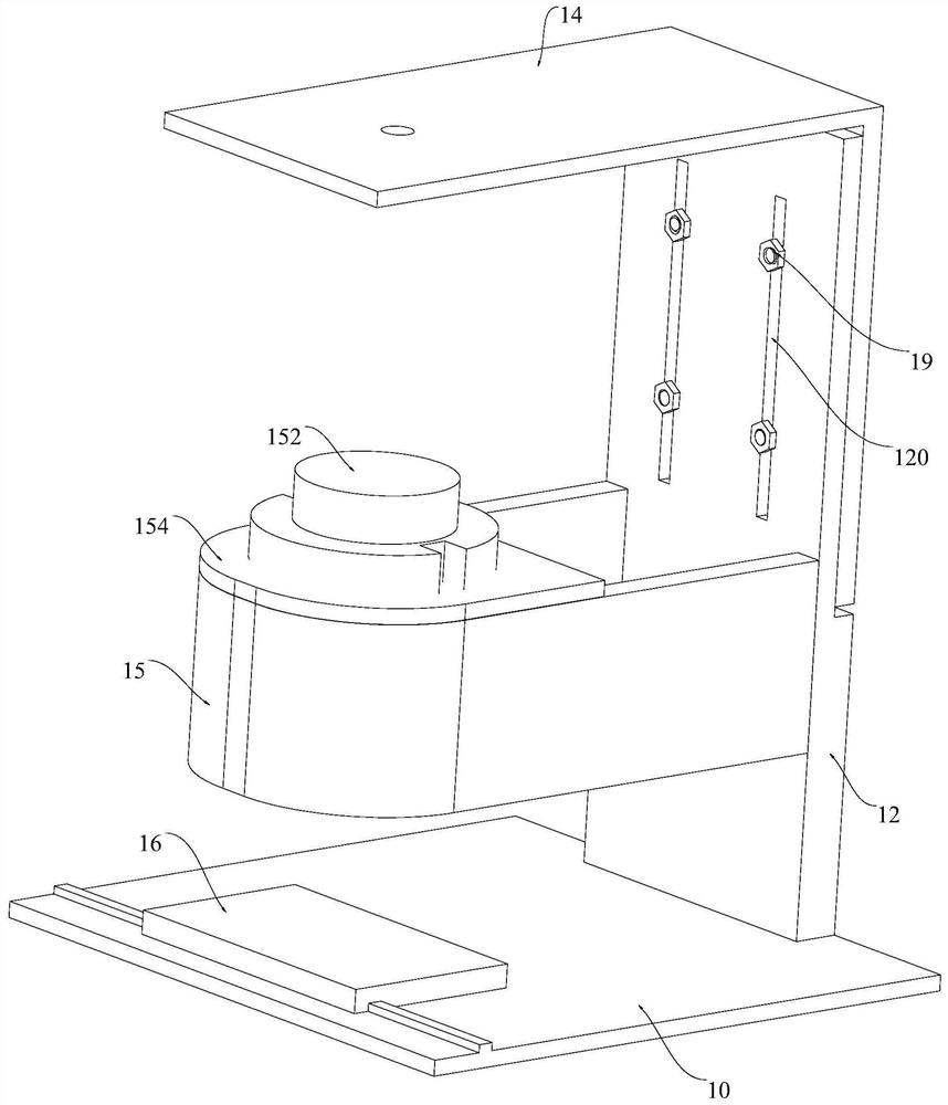
[0064] like figure 1 and figure 2 As shown, the click test device provided by the embodiment of the present application includes a frame 1 , a driving ...


PUM


Abstract

The invention provides a click test device. The click test device comprises a rack, a driving mechanism, a transmission mechanism and a pressure head assembly, the driving mechanism is connected to the rack, the driving mechanism comprises a power output shaft, and the power output shaft can output torsion power; the transmission mechanism comprises a first part and a second part which abut against each other, and the first part and the second part are sequentially arranged in the axial direction of the power output shaft. The first part is fixedly connected to the power output shaft, the second part is connected to the rack in a sliding mode, and the end, opposite to the second part, of the first part is of a non-planar structure so that rotation of the first part can be converted into linear movement of the second part; the pressing head assembly is connected to the second part, and the second part drives the pressing head assembly to move in a reciprocating mode. The structure of the click test device can be simplified, and the stability and reliability of the click test device can be improved.

Description

technical field [0001] The present application relates to the technical field of electronic equipment, in particular to a click test device. Background technique [0002] In the research and development stage of mobile phones and other electronic products, stress reliability tests based on user scenarios are required, such as sliding, clicking, micro-vibration and pressing, etc., which can effectively stimulate the weak points of the mobile phone display and internal structure, and identify product failure risks in advance. Improvement is critical. [0003] With the popularization of mobile phone full-screen design and the acceleration of related product iterations, R&D personnel have further increased the requirements for agility and consistency verification of click tests. The existing technology has long fixed installation time of indenters, easy interference between mechanisms, and low test efficiency. , high maintenance and debugging costs. For example, the patent "a ...

Claims


Application Information

Patent Timeline
IPC IPC(8): G01M13/00
CPCG01M13/00
Inventor 骈亚威苗水壮张军王世峰
Owner BEIJING HONOR DEVICE CO LTD
Learn More