
Magnetic suspension type electric power measuring device

A dynamometer device and magnetic levitation technology, which is applied in measuring devices, dynamometers, instruments, etc., can solve the problems that the electric dynamometer operation of the motor under test, the centering clamping of the motor under test, and the safety protection cannot be solved.

Pending Publication Date: 2022-02-25
HANGZHOU WEIHENG TECH
View PDF0 Cites 0 Cited by
  • Summary
  • Abstract
  • Description
  • Claims
  • Application Information

AI Technical Summary

Problems solved by technology

[0004] The purpose of the present invention is to provide a magnetic levitation electric dynamometer to solve the problems of inability to protect safety, inability to perform electric dynamometer operation on different specifications of motors under test and inability to perform centering clamp on the motor under test proposed in the above background technology. tight question

Method used


Image

  • Magnetic suspension type electric power measuring device
  • Magnetic suspension type electric power measuring device
  • Magnetic suspension type electric power measuring device

Examples


Embodiment Construction

[0029]The following will clearly and completely describe the technical solutions in the embodiments of the present invention with reference to the accompanying drawings in the embodiments of the present invention. Obviously, the described embodiments are only some, not all, embodiments of the present invention. Based on the embodiments of the present invention, all other embodiments obtained by persons of ordinary skill in the art without making creative efforts belong to the protection scope of the present invention.

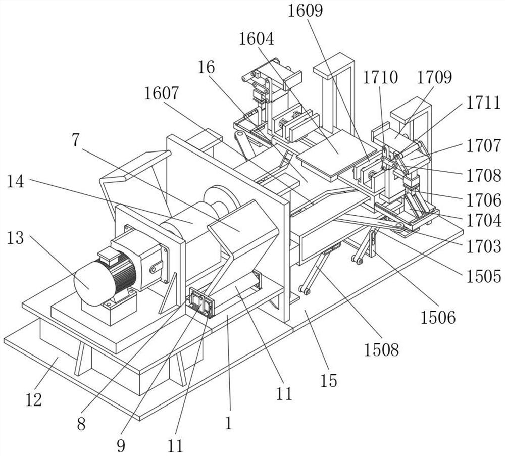
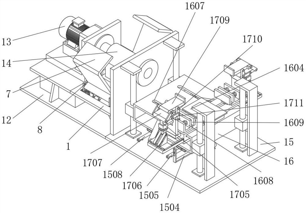
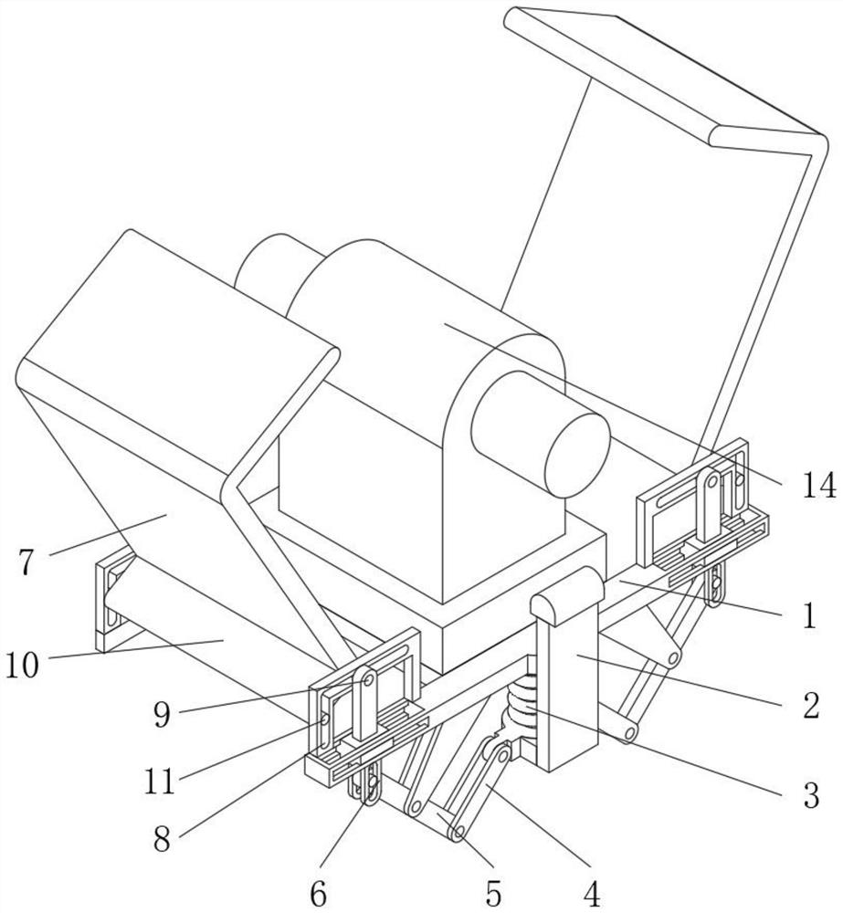
[0030] see Figure 1-8 , in an embodiment of the present invention, a magnetic levitation type electric dynamometer includes a protective frame 1, a swing plate 5, a protective plate 7 and a guide plate 8, the inner wall of the protective frame 1 runs through a pulling plate 2, and the bottom end of the pulling plate 2 The working spring 3 that is fixedly connected with the inner wall of the protective frame 1 is fixedly connected, the side wall of the pull pla...


PUM


Abstract

A magnetic suspension type electric power measuring device disclosed by the present invention comprises a protection frame, a swing plate, a protection plate and a guide plate, a pulling plate penetrates through the inner wall of the protection frame, and the bottom end of the pulling plate is fixedly connected with a working spring fixedly connected with the inner wall of the protection frame. The side wall of the pulling plate is rotationally connected with swinging connecting rods for driving the swinging plate to vertically rotate. According to the magnetic suspension type electric power measuring device, through the arrangement of a sliding guide column and a driven guide column, in the protection frame, the pulling plate moves to drive the two sets of swing plates to swing relatively through the two sets of swing connecting rods, the swing plate swings to drive the sliding guide column to slide along the outer wall of the protection frame through the sliding hole plate, the sliding guide column drives the overturning guide plate to slide along the inner wall of the guide guide plate, meanwhile, the overturning guide plate moves to drive the driven guide column to slide along the inner wall of the guide guide plate, the overturning guide plate moves to drive the protection plate to move, and closing operation of the protection plate is achieved.

Description

technical field [0001] The invention relates to the field of electric dynamometer, in particular to a magnetic levitation electric dynamometer. Background technique [0002] The AC power dynamometer is the most advanced loading dynamometer equipment on the market. The power dynamometer adopts AC frequency conversion feedback loading, and the loading energy is fed back to the power grid through the AC load generator; the torque and speed are directly measured by the torque sensor; the power comprehensive measuring instrument detects Current, voltage, frequency, power factor, etc.; the computer automatically detects, displays and completes data processing, reports and various curves. [0003] However, the existing magnetic levitation electric dynamometer has the problem that it cannot be safely protected during use, which makes it difficult to install the motor under test, and the existing magnetic levitation electric dynamometer cannot be used for different specifications. T...

Claims


Application Information

Patent Timeline
IPC IPC(8): G01L3/24
CPCG01L3/24
Inventor 朱庆王江峰路国卫郎向荣
Owner HANGZHOU WEIHENG TECH
Learn More