
Technology for improving flatness of fusion zone

A technology of flatness and fusion, applied in multilayer circuit manufacturing, electrical components, printed circuit manufacturing, etc.

Pending Publication Date: 2022-02-18
宏华胜精密电子(烟台)有限公司
View PDF0 Cites 0 Cited by
  • Summary
  • Abstract
  • Description
  • Claims
  • Application Information

AI Technical Summary

Problems solved by technology

[0006] In view of the deficiencies in the existing technology, the purpose of the present invention is to provide a technology to improve the flatness of the fusion zone, which solves the problem that each core of the copper-free square PAD in the copper block of the fusion zone overlaps in the direction of the Z axis

Method used


Image

  • Technology for improving flatness of fusion zone
  • Technology for improving flatness of fusion zone
  • Technology for improving flatness of fusion zone

Examples


Embodiment 1

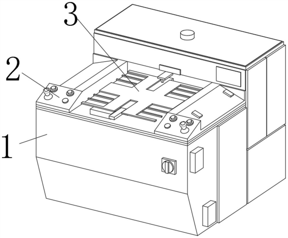
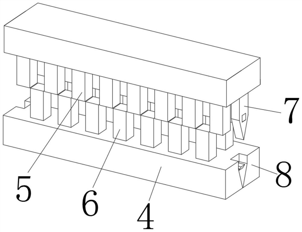
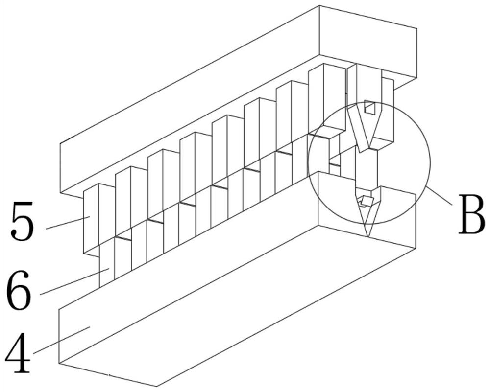
[0028] see Figure 1-4 , the present invention provides a technical solution: a device for improving the flatness of the fusion zone, including a body 1 and two copper blocks 4, and the two copper blocks 4 are fixedly installed inside the body 1, and the body 1 A console 2 and an operating table 3 are fixedly installed on the top, and the sides of the two copper blocks 4 close to each other are fixedly connected to the first slider 5 and the second slider 6 respectively, and the first slider 5 and the second slider The blocks 6 are evenly distributed on the surface of the two copper blocks 4, the first slider 5 and the second slider 6 are staggered and slidably installed with each other, and the side of the copper block 4 close to the first slider 5 is fixed A block 9 is installed, and the inside of the copper block 4 is provided with a chute 8, and the inner wall of the chute 8 is fixedly connected with a block 9, and the inside of the block 9 is provided with a fitting that ...

Embodiment 2

[0031] like Figure 1-4 As shown, on the basis of Embodiment 1, the present invention provides a technical solution: the bottom end of the plug-in block 7 is slidingly connected with the inside of the chute 8, and there are at least two plug-in blocks 7, and the two plug-in blocks 7 are made of copper block 4 The distribution is axisymmetric, and the dimensions on the surface of the insert block 7 are compatible with those of the inner wall of the chute 8.

[0032] In this embodiment, when the first slider 5 is pressed down, the inserted block 7 is inserted into the chute 8 to limit the position, and the first slider 5 and the second slider 6 are controlled by the plug 7 and the chute 8. Auxiliary alignment to avoid the current generated by the copper block 4 in the high-frequency magnetic field. Once the position of the two copper-free PADs deviates, it will easily lead to damage to the body 1 and materials, and increase the risk of operation. Two The clamping block 9 is stu...


PUM


Abstract

The invention discloses a technology for improving flatness of fusion zone. The technology comprises a machine body and two copper blocks, a control table and an operation table are fixedly installed at the top of the machine body, the sides, close to each other, of the two copper blocks are fixedly connected with a first sliding block and a second sliding block correspondingly, and two clamping plates are connected to the two sides of each copper block in a clamped mode; a connecting ring is fixedly mounted on the sides, close to each other, of the two clamping plates, a threaded rod is in threaded connection with the inner wall of the connecting ring, a rotating shaft is fixedly mounted on one side of the threaded rod, a first gear is fixedly connected to the surface of the rotating shaft, and a second gear is engaged with the top of the first gear; and a motor is fixedly mounted at one end of the second gear. The first sliding blocks and the second sliding blocks are arranged in a staggered mode, and the copper blocks in the fusion area are designed in a latticed staggered mode, so that the phenomena that in the fusion process, latticed design is completely overlapped, the positions of heating heat of the copper blocks are concentrated, and the fusion area is heated unevenly are avoided.

Description

technical field [0001] The invention belongs to the technical field of electromagnetic fusion machines, and in particular relates to a technology for improving the flatness of a fusion zone. Background technique [0002] With the development of my country's PCB industry, the requirements for PCB boards, especially for the quality of multilayer circuit boards, are getting higher and higher. In this way, the capabilities of production equipment, including equipment functions, operation and maintenance, appearance, energy saving, etc. The demand in this area is also constantly increasing, and the interlayer fusion of multilayer circuit boards is often fused by a high-frequency electromagnetic fusion machine. [0003] When the traditional electromagnetic fusion machine is in use: [0004] 1. Since the copper-free square PAD in the copper block in the fusion zone overlaps each core in the direction of the Z axis, the grid-like design in the fusion process is completely overlapped...

Claims


Application Information

Patent Timeline
Patent Type & Authority Applications(China)
IPC IPC(8): H05K3/46
CPCH05K3/4611
Inventor 马新伟
Owner 宏华胜精密电子(烟台)有限公司
Learn More