Insoluble particle detection assembly line

An assembly line and particle technology, applied in the direction of measuring devices, particle size analysis, particle and sedimentation analysis, etc., can solve problems such as inability to detect in batches, blockage, and unexpected situations

Active Publication Date: 2022-02-18
ZHEJIANG UNIV
View PDF10 Cites 0 Cited by
  • Summary
  • Abstract
  • Description
  • Claims
  • Application Information

AI Technical Summary

Problems solved by technology

[0003] The preparation of medicinal liquid in the hospital refers to the mixing of medicinal liquid with saline or sugar water and other solvents to form a mixed medicinal liquid that is finally input into the patient's body, and the medicinal liquid is divided into solid Powder or liquid medicine, the configuration of solid medicine powder is to extract a part of the solvent and inject it into the powder bottle for mixing and shaking to form the initial medicine liquid. Medical staff usually use the method of naked eye observation to see if there are foreign objects visible to the naked eye in the medicine liquid. If there is no The initial drug solution will be injected back into the solvent bottle or solvent bag. If there are visible foreign objects, it needs to be reconfigured to avoid accidents when infusing patients. However, visual inspection is far from enough. Human capillaries are the most The diameter of the fine part is only 7-12 μm, and the insoluble particles can directly block it, causing very serious consequences
[0004] In the prior art, photoresistive particle counters are used to detect insoluble particles in the liquid medicine, but the number of patients in the hospital is huge, and the prior art cannot be carried out in batches detection, very inconvenient

Method used


Image

  • Insoluble particle detection assembly line
  • Insoluble particle detection assembly line
  • Insoluble particle detection assembly line

Examples


Embodiment Construction

[0027] The following are specific embodiments of the present invention and in conjunction with the accompanying drawings, further describe the technical solution of the present invention, but the present invention is not limited to these embodiments.

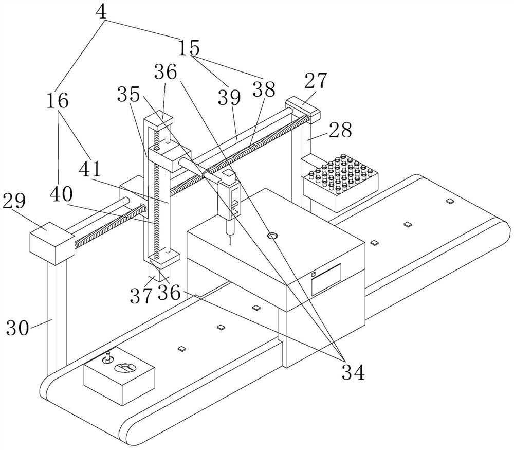
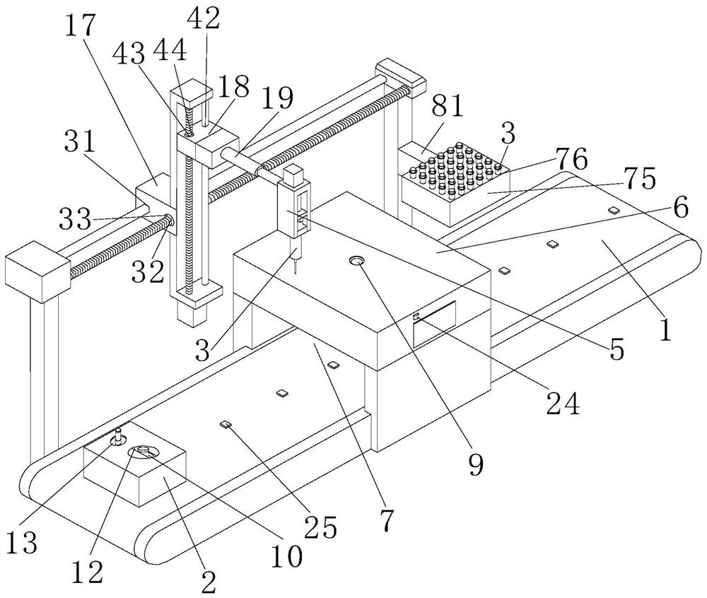
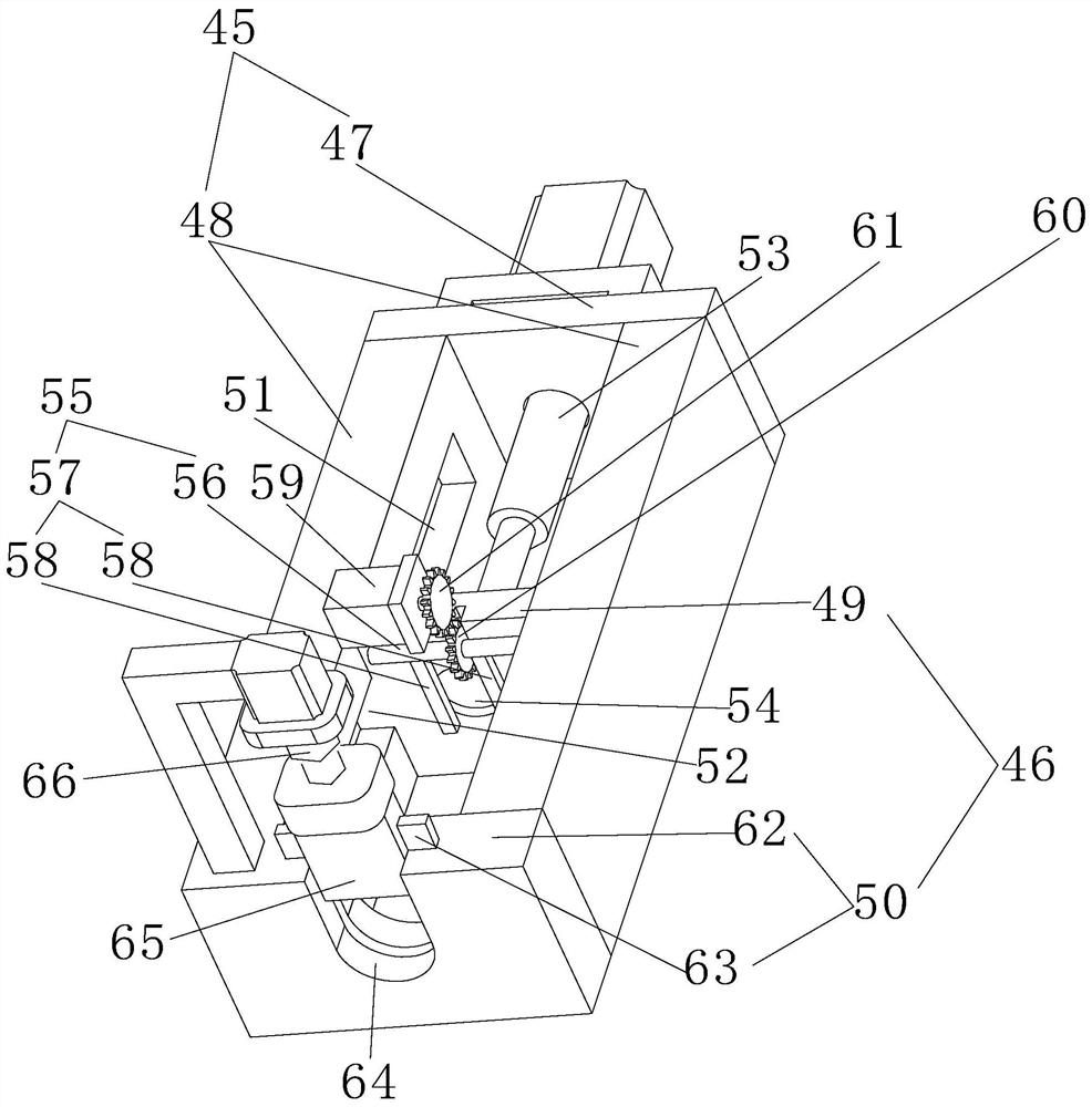
[0028] Such as Figure 1-Figure 8 As shown, the insoluble particle detection assembly line includes a conveyor belt 1, a feeding box 2, a syringe 3, a moving mechanism 4, a control device 5, and a photoresisting method detection device 6. The syringe of the syringe 3 is transparent, and the photoresisting method detection device 6 It is arranged above the conveyor belt 1, and there is a passageway 7 for the material box 2 to pass between the photoresistance method detection device 6 and the conveyor belt 1. The photoresistance method detection device 6 is internally provided with a sample channel 8, a processing device 20, a laser The transmitter 21 and the light receiving plate 22, the laser emitter 21 and the light receiving p...


PUM

PropertyMeasurementUnit
diameteraaaaaaaaaa

Abstract

The invention provides an insoluble particle detection assembly line, and belongs to the technical field of detection assembly lines. Batch detection cannot be realized in the prior art. A laser transmitter and a light receiving plate are located at the two sides of a sample channel respectively, the laser transmitter is used for transmitting light to penetrate through the sample channel to reach the light receiving plate, the light receiving plate sends signals to a processing device through a photoelectric converter, the sample channel is used for containing an injector, and the length of the sample channel is the same as that of a needle cylinder of an injector. Openings communicated with the sample channel are formed in the top and the bottom of a light resistance method detection device, when a material containing box is located at the bottom of the light resistance method detection device, a bottle opening of a solvent bag or a solvent bottle on the material containing box coincides with the opening in the bottom of the light resistance method detection device, and a control device is used for controlling the injector to extract and inject liquid. A storage groove and a vibration groove are formed in the top of the material containing box, a containing table used for containing medicine powder bottles and a vibration device used for shaking the containing table are arranged in the vibration groove, so that batch detection can be achieved.

Description

technical field [0001] The invention belongs to the technical field of detection assembly line, in particular to an insoluble particle detection assembly line. Background technique [0002] The Light Blockage method, also known as the Light Blockage method or the Light Blockage method, is a method for detecting the particle size by using the change in light intensity caused by the blocking of light by particles, and the detection range is from 1 μm to 2.5 mm. [0003] The preparation of liquid medicine in the hospital refers to mixing the medicine with solvents such as saline or sugar water to form a mixed medicine liquid that is finally input into the patient's body, and the medicine is divided into solid medicine powder or liquid medicine liquid. The configuration of the solid medicine powder is to first extract the solvent Part of it is injected into the powder bottle, mixed and shaken to form the initial liquid medicine. Medical staff usually use the method of naked eye ...

Claims


Application Information

Patent Timeline
Patent Type & Authority Applications(China)
IPC IPC(8): G01N15/02
CPCG01N15/0205
Inventor 吴圣洁
Owner ZHEJIANG UNIV
Why Eureka
Try Eureka