Unmanned aerial vehicle thickness measuring system based on electromagnetic ultrasonic technology

An electromagnetic ultrasonic and unmanned aerial vehicle technology, applied in the direction of electromagnetic measuring devices, electric/magnetic thickness measurement, using electromagnetic means, etc., can solve problems that affect the construction progress and generate greater risks, so as to improve coverage and reduce detection costs and artificial risk, the effect of light weight

Pending Publication Date: 2022-02-18
零声科技(苏州)有限公司
View PDF0 Cites 0 Cited by
  • Summary
  • Abstract
  • Description
  • Claims
  • Application Information

AI Technical Summary

Problems solved by technology

[0003] In order to solve the problem of on-site detection by erecting scaffolding, which not only affects the construction progress, but also causes greater risks due to weather and geological conditions, the present invention proposes a UAV thickness measurement system based on electromagnetic ultrasonic technology

Method used


Image

  • Unmanned aerial vehicle thickness measuring system based on electromagnetic ultrasonic technology
  • Unmanned aerial vehicle thickness measuring system based on electromagnetic ultrasonic technology
  • Unmanned aerial vehicle thickness measuring system based on electromagnetic ultrasonic technology

Examples


specific Embodiment approach 1

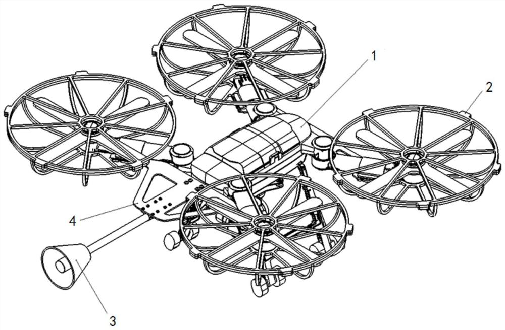
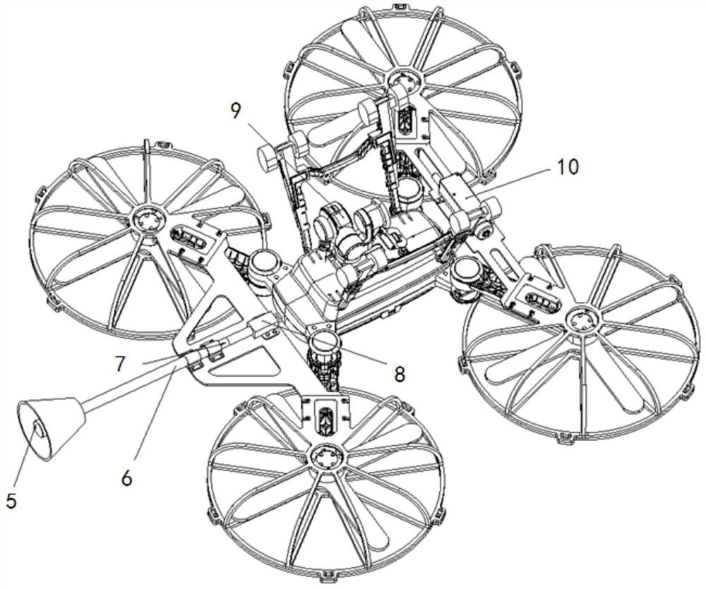
[0016] Specific implementation mode one: combine Figure 1 to Figure 3 Describe this embodiment, a kind of UAV thickness measurement system based on electromagnetic ultrasonic technology described in this embodiment, it includes UAV platform 1; This embodiment also includes electromagnetic ultrasonic sensor 5, image transmission module 9, electromagnetic Thick module 10 and first connection assembly; Electromagnetic ultrasonic sensor 5 is installed on the front end of unmanned aerial vehicle platform 1 through described first connection assembly, and image transmission module 9 is installed in the middle part in unmanned aerial vehicle platform 1, and electromagnetic ultrasonic thickness measuring module 10 is mounted on the rear of the unmanned aerial vehicle platform 1.

[0017] In this embodiment, the UAV platform 1 is also provided with a sensor control module; the sensor control module includes a pull-out sensor and a semi-flexible connection follow-up of the sensor. Sem...

specific Embodiment approach 2

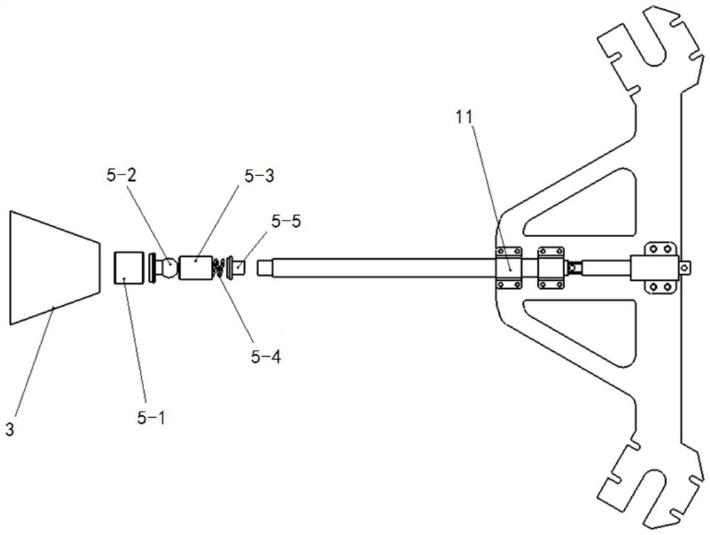
[0018] Specific implementation mode two: combination Figure 1 to Figure 3 To illustrate this embodiment, the first connection assembly of an unmanned aerial vehicle thickness measurement system based on electromagnetic ultrasonic technology in this embodiment includes a first connector 4, a slide tube 6, a telescopic rod 7 and a power unit 8; A connector 4 is fixedly installed on the front end of the UAV platform 1, the power unit 8 is fixedly installed on the first connector 4, the electromagnetic ultrasonic sensor 5 is installed on the front end of the slide tube 6, and the rear end of the slide tube 6 passes through the telescopic rod 7 It is connected with the power unit shaft of the power unit 8. Other components and connections are the same as those in the first embodiment.

specific Embodiment approach 3

[0019] Specific implementation mode three: combination Figure 1 to Figure 3 To illustrate this embodiment, a UAV thickness measurement system based on electromagnetic ultrasonic technology described in this embodiment also includes a probe cover 3; superior. Other compositions and connections are the same as those in Embodiment 1 or 2.


PUM


Abstract

The invention discloses an unmanned aerial vehicle thickness measuring system based on an electromagnetic ultrasonic technology, and relates to an unmanned aerial vehicle thickness measuring system. The invention aims to solve the problems that on-site detection is carried out by erecting a scaffold, the construction progress is influenced, and large risks can be generated due to weather and geological condition images. The system comprises an unmanned aerial vehicle platform, and further comprises an electromagnetic ultrasonic sensor, an image transmission module, an electromagnetic ultrasonic thickness measuring module and a first connecting assembly. The electromagnetic ultrasonic sensor is installed at the front end of the unmanned aerial vehicle platform through the first connecting assembly, the image transmission module is installed in the middle of the unmanned aerial vehicle platform, and the electromagnetic ultrasonic thickness measurement module is installed in the rear of the unmanned aerial vehicle platform. The invention belongs to the field of nondestructive testing.

Description

technical field [0001] The invention relates to an unmanned aerial vehicle thickness measurement system, in particular to an unmanned aerial vehicle thickness measurement system based on electromagnetic ultrasonic technology, which belongs to the field of non-destructive testing. Background technique [0002] Whether it is outdoors or indoors, scaffolding needs to be set up for inspection in most inspection scenarios. At this time, setting up scaffolding will increase manpower and material resources, and there will be greater safety risks during the erection, use, and dismantling of scaffolding. The erection and removal of scaffolding The process will also affect the construction progress of the site and increase the construction time; the increased risk, construction period, and cost of erecting and dismantling scaffolding outdoors, especially when the weather is bad and the geological conditions are poor, are often greater; there are some overhead positions of key pipelines...

Claims


Application Information

Patent Timeline
Patent Type & Authority Applications(China)
IPC IPC(8): G01B17/02G01B7/06B64C39/02
CPCG01B17/02G01B7/10B64C39/024B64U2101/00
Inventor 吴勇锋李永虔李展鹏许霁汪开灿
Owner 零声科技(苏州)有限公司
Why Eureka
Try Eureka