
Computed tomography spinal fracture auxiliary diagnosis system

A tomography, auxiliary diagnosis technology, applied in computer-aided medical procedures, computer parts, computing and other directions, can solve the problems of inconspicuous symptoms, small scope, hidden features, etc., to reduce learning difficulty, improve model performance, and improve accuracy. rate effect

Inactive Publication Date: 2022-02-15
MEI HOSPITAL UNIV OF CHINESE ACAD OF SCI
View PDF0 Cites 1 Cited by
  • Summary
  • Abstract
  • Description
  • Claims
  • Application Information

AI Technical Summary

Problems solved by technology

However, in practice, these two methods will be affected by the subjective factors of the diagnostician to varying degrees, and early single vertebral fractures usually have the characteristics of small range, hidden features, and indistinct symptoms, resulting in high missed diagnosis of manual diagnosis. rate problem
[0004] Auxiliary diagnosis of vertebral fractures requires positioning of the vertebral body of the spine. The existing public technology "Using Spatial Configuration Network and U-shaped Network for Vertebral Body Positioning and Segmentation from Coarse to Fine" (Payer, Christian, et al ."Coarse to Fine Vertebrae Localization and Segmentation withSpatialConfiguration-Net and U-Net."VISIGRAPP(5:VISAPP).2020.) introduces a spinal vertebral positioning method, which uses U-Net to locate the approximate position of the spine , and then through a vertebral positioning network to return the positioning and numbering of each vertebra. Finally, U-Net performs fine-grained binary segmentation on each identified vertebra, and then combines the individual predictions into the final multi-label vertebral segmentation. , has solved the problem of vertebral body positioning well; but it only completes the work of vertebral body positioning, and does not solve the problem of auxiliary diagnosis of vertebral body fractures

Method used


Image

  • Computed tomography spinal fracture auxiliary diagnosis system
  • Computed tomography spinal fracture auxiliary diagnosis system
  • Computed tomography spinal fracture auxiliary diagnosis system

Examples


Embodiment Construction

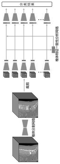
[0032] The auxiliary diagnosis system takes the original CT image containing the spine as input, and fuses and compares and analyzes the feature images of multiple vertebral bodies through a neural network, so as to help the model identify vertebral bodies with abnormal features. At the same time, the feature information of vertebral bodies with known fracture levels is introduced as a reference for neural network fusion and comparison. The above design effectively utilizes the information of multiple vertebral bodies of the spine in CT images, so that the model can play a good role in the diagnosis of spinal fractures based on CT images.

[0033] Because CT images have the characteristics of high resolution and large amount of information, this model uses a two-stage network to analyze CT images. The analysis process includes two stages of vertebral body positioning and segmentation and classification and diagnosis.

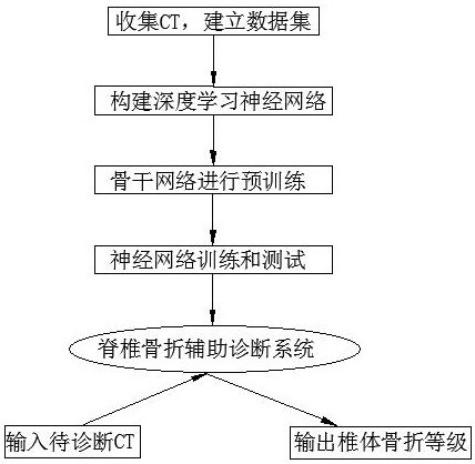
[0034] like figure 1 and figure 2 As shown, a computeri...


PUM


Abstract

The invention discloses a computed tomography spinal fracture auxiliary diagnosis system. The system comprises the following steps: step 1, collecting CT images, marking the CT images, and arranging the CT images into a data set; step 2, constructing a deep learning neural network based on multi-segment consistency constraint, wherein the deep learning neural network comprises positioning and marking of a spine centrum and diagnosis of a spine fracture level; step 3, pre-training the backbone network; step 4, training and testing the neural network; and step 5, inputting a CT image to be diagnosed into the trained network, and outputting a diagnosis result. The method has the advantages that: the spine image information is subjected to feature extraction through the two-stage network, a subsequent consistency analysis module is helped to pay attention to the spine centrum information, and a consistency comparison module is introduced, so that the model learning difficulty is remarkably reduced, the model performance is improved, and the diagnosis accuracy is improved.

Description

technical field [0001] The invention relates to the technical field of medical image processing and auxiliary diagnosis, in particular to a computer tomography scanning vertebral fracture auxiliary diagnosis system. Background technique [0002] Computed tomography (CT), as a high-definition stereoscopic medical image, plays an important role in the screening and diagnosis of various diseases. In recent years, with the continuous development of computer technology and deep learning technology, computer vision-aided diagnosis systems have made certain achievements in the identification of vertebral fractures. [0003] Genant semi-quantitative and quantitative methods are commonly used methods for evaluating vertebral fractures. However, in practice, these two methods are affected by the subjective factors of the diagnosers to varying degrees, and the early fractures of a single vertebral body usually have the characteristics of small scope, hidden features, and inconspicuous...

Claims


Application Information

Patent Timeline
Patent Type & Authority Applications(China)
IPC IPC(8): G16H50/20G06T7/00G06K9/62G06V10/774G06V10/26
CPCG16H50/20G06T7/0012G06T7/0014G06T2207/10081G06T2207/20081G06T2207/20084G06F18/22G06F18/214
Inventor 李劲鹏魏鑫从怀威王杰蔡挺
Owner MEI HOSPITAL UNIV OF CHINESE ACAD OF SCI
Learn More