
Deep hole speed-up gear box

A gearbox and deep hole technology, which is applied in the directions of gear lubrication/cooling, belt/chain/gear, transmission box, etc., can solve the problem of inconvenient assembly and operation of the gearbox, and achieve improved convenience, smoothness, and improved sealing Effect

Pending Publication Date: 2022-02-15
ZHEJIANG BUSINESS TECH INST
View PDF0 Cites 0 Cited by
  • Summary
  • Abstract
  • Description
  • Claims
  • Application Information

AI Technical Summary

Problems solved by technology

[0005] In order to make up for the deficiencies of the existing technology, the existing gearbox is not easy to assemble and operate, the present invention proposes a deep-hole speed-increasing gearbox

Method used


Image

  • Deep hole speed-up gear box
  • Deep hole speed-up gear box
  • Deep hole speed-up gear box

Examples


Embodiment 1

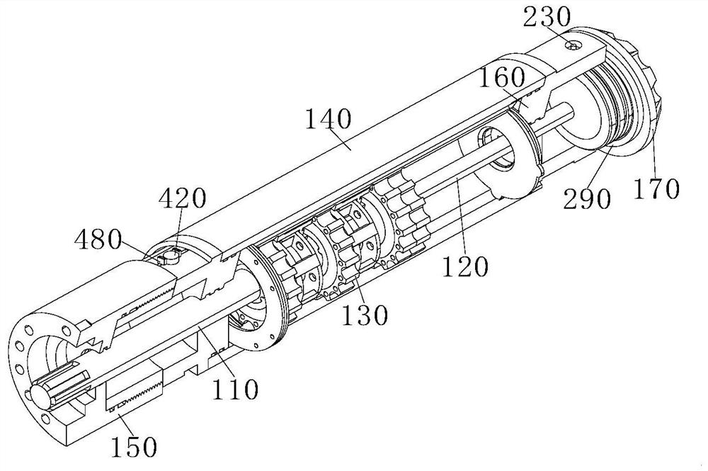
[0031] see Figure 1-7 As shown, the deep hole speed-up gearbox includes a high-speed shaft 110, an output shaft 120, a speed-up conversion assembly 130, and an output port interface 170; the high-speed shaft 110 and the output shaft 120 are connected through a speed-up conversion assembly 130, so A high-speed bearing support 150 is sleeved on the outside of the high-speed rotating shaft 110, an output bearing support 160 is sleeved on the outside of the output rotating shaft 120, a housing 140 is arranged between the high-speed bearing support 150 and the output bearing support 160, and one end of the output port 170 Inserted inside the other end of the output bearing support 160;

[0032] The upper and lower ends of the output bearing support 160 are provided with a splicing mechanism. The splicing mechanism includes a threaded rod 210, a transmission assembly 220, a handle 230, a support assembly 280 and a positioning structure. Inside the upper and lower ends of the bearing...


PUM


Abstract

The invention belongs to the field of mechanical engineering, and particularly relates to a deep hole speed-up gear box which comprises a high-speed rotating shaft, an output rotating shaft, a speed-up conversion assembly and an output end connector. The high-speed rotating shaft and the output rotating shaft are connected through the speed-up conversion assembly, a high-speed bearing supportsleeves the high-speed rotating shaft, and an output bearing support sleeves the output rotating shaft; a shell is arranged between the high-speed bearing support and the output bearing support, and one end of the output end connector is inserted into the other end of the output bearing support. According to the gear box, the problem that parts of the gear box are inconvenient to splice is solved; an operator can splice and fix the shell, the high-speed bearing support, the output bearing support and the output end connector conveniently through a splicing mechanism, so that the operation convenience is improved; the sealing performance between the parts is improved at the same time through the design of a sealing ring and a sealing sleeve, and a dust-proof effect is realized, so that the service life of the gear box is prolonged.

Description

technical field [0001] The invention relates to the field of mechanical engineering, in particular to a deep-hole speed-increasing gearbox. Background technique [0002] A wind turbine is a power device that converts wind energy into mechanical work, which drives the rotor to rotate and finally outputs alternating current. The gearbox is an important mechanical component that is widely used in wind turbines. Its main function is to turn the wind wheel The power generated under the action of wind is transmitted to the generator and makes it obtain the corresponding speed. Usually the speed of the wind wheel is very low, far below the speed required by the generator to generate electricity, and must be realized through the speed-up effect of the gear pair of the gearbox. [0003] The deep-hole speed-increasing gearbox is a kind of gearbox, which is the reverse motion of the reduction gearbox. Its main feature is that the high-speed shaft is thick and the output shaft is small...

Claims


Application Information

Patent Timeline
Patent Type & Authority Applications(China)
IPC IPC(8): F16H57/02F16H57/021F16H57/029F16H57/038F16H57/031F16H57/04F16N21/06F03D15/00
CPCF16H57/02F16H57/021F16H57/029F16H57/038F16H57/031F16H57/0424F16N21/06F03D15/00F16H2057/02078Y02E10/72
Inventor 肖国华
Owner ZHEJIANG BUSINESS TECH INST
Learn More