
Counting driving device and three-position switch operating mechanism

A three-position switch and drive device technology, applied in electrical switches, air switch parts, high-voltage air circuit breakers, etc., can solve the problem of inconvenient observation of the counter, complex counting and drive devices, and reducing the efficiency of the service life of the three-position switch and other problems, to achieve the effect of easy observation, reasonable layout, and improved efficiency

Pending Publication Date: 2022-05-13
GUANGZHOU BAIYUN ELECTRIC EQUIP
View PDF0 Cites 0 Cited by
  • Summary
  • Abstract
  • Description
  • Claims
  • Application Information

AI Technical Summary

Problems solved by technology

However, the existing counting drive device is relatively complicated, and it is difficult to make the counter and the three-position switch operating mechanism form an organic whole, which will directly affect the overall shape and size of the three-position switch operating mechanism, and sometimes even cause the three-position switch to operate. The moving mechanism cannot be installed and used in some places
In addition, the existing counting drive device is usually not convenient for the staff to observe the counter, which reduces the efficiency of the staff to obtain the service life of the three-position switch

Method used


Image

  • Counting driving device and three-position switch operating mechanism
  • Counting driving device and three-position switch operating mechanism
  • Counting driving device and three-position switch operating mechanism

Examples


Embodiment Construction

[0030] The technical solutions of the present invention will be clearly and completely described below in conjunction with the embodiments. Obviously, the described embodiments are part of the embodiments of the present invention, but not all of them. Based on the embodiments of the present invention, all other embodiments obtained by persons of ordinary skill in the art without making creative efforts belong to the protection scope of the present invention.

[0031] At present, the three-position switch operating mechanism usually does not reserve an installation position for the counter, and it is necessary to install some auxiliary components on the three-position switch operating mechanism to complete the installation of the counter, thereby forming a counting drive device.

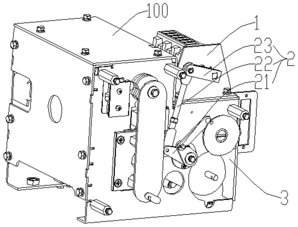
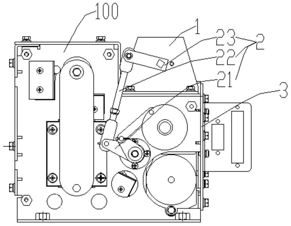
[0032] Specifically, with figure 1 and figure 2 As an example, the local structure of a three-position switch operating mechanism in the prior art is described as follows: a three-position switch op...


PUM


Abstract

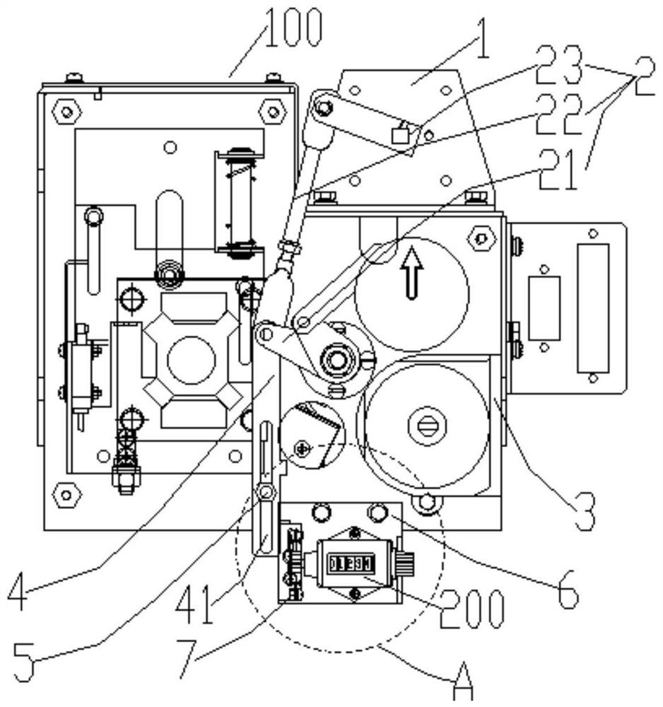
The invention provides a counting driving device and a three-position switch operating mechanism. The counting driving device comprises a counter push rod, a counter fixedly installed on the upper portion of one side of the three-position switch operating mechanism and a counter crank arm rotatably installed on one side of the counter. The counter push rod and one side of the three-position switch operating mechanism form a guide structure along the length direction of the counter push rod; a blocking arm is fixedly arranged on one side of the counter push rod; the upper end of the counter push rod is rotatably connected with a crank rocker mechanism on the three-position switch operating mechanism; the crank rocker mechanism is used for driving the counter push rod to move, so that the blocking arm pushes the counter crank arm to achieve counting of the counter. According to the invention, the counter and the three-position switch operating mechanism can form an organic whole, and the convenience of observing the counter by a worker is improved, so that the efficiency of obtaining the service life of the three-position switch by the worker is improved on the premise of not influencing the normal work of the three-position switch operating mechanism.

Description

technical field [0001] The invention relates to the technical field of electrical engineering, in particular to a counting drive device and a three-position switch operating mechanism. Background technique [0002] The three-position switch is an important component in the power industry. It has three positions: closing, isolation, and grounding. Among them, closing is used to connect the circuit, isolation is used to disconnect the circuit and form a clear fracture, and grounding is used for Ground the main circuit and release the residual charge so that maintenance personnel can overhaul the circuit. The three-position switch is mainly composed of an isolating knife and an operating mechanism. The rotation of the isolating knife realizes the conversion of the three-position switch in the closing, isolating and grounding positions. The service life of the three-position switch can usually be expressed by the number of opening and closing times of the three-position switch....

Claims


Application Information

Patent Timeline
Patent Type & Authority Applications(China)
IPC IPC(8): H01H31/02H01H9/16
CPCH01H31/026H01H9/16
Inventor 邱杰生刘清扬程咏斌崔鹏侯立伟李元鹏
Owner GUANGZHOU BAIYUN ELECTRIC EQUIP
Learn More