Guide rail supporting device

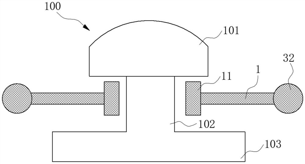
A technology of a supporting device and a guide rail, which is applied in the field of guide rails, can solve the problems of lateral displacement of the I-shaped rail 100, inability to effectively lift the I-shaped rail 100, and laborious lifting of the I-shaped rail 100.

Pending Publication Date: 2022-02-11
GUANGDONG POWER GRID CO LTD +1
View PDF4 Cites 0 Cited by
  • Summary
  • Abstract
  • Description
  • Claims
  • Application Information

AI Technical Summary

Problems solved by technology

In the traditional way, in order to raise or lower the I-shaped rail 100, the I-shaped rail 100 is pried up from the bottom 103 of the guide rail by using a support rod or an iron rod to raise the ground or dig the ground. One side of the bottom 103 protrudes below the bottom 103 of the guide rail. It is very laborious to lift the I-shaped rail 100 and it is very easy to cause the lateral deviation of the I-shaped rail 100, which cannot effectively lift the I-shaped rail 100.

Method used


Image

  • Guide rail supporting device
  • Guide rail supporting device
  • Guide rail supporting device

Examples


Embodiment 1

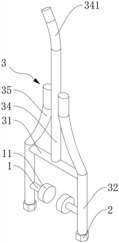
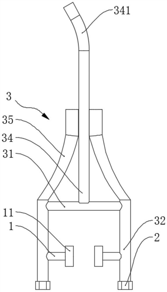
[0039] figure 1 A schematic structural view of the I-shaped rail 100 in the prior art is shown, and the specific structure of the I-shaped rail 100 has been described in detail in the background art. figure 2 A schematic structural view of the guide rail support device in this embodiment is shown, image 3 A schematic front view of the rail support device in this embodiment is shown. refer to Figure 1-Figure 3 , this embodiment provides a guide rail support device for supporting the I-shaped rail 100, which can be used in the field of guide rail technology, and can be erected on both sides of the I-shaped rail 100 to complete the lifting of the I-shaped rail 100.

[0040] Continue to refer to Figure 1-Figure 3 , the guide rail support device includes a support frame 3, a guide rail support 1 and a ground support 2, two guide rail supports 1 are provided, and the two guide rail supports 1 are fixedly connected with the support frame 3 respectively, and can be respectively...

Embodiment 2

[0051] Figure 4 A schematic structural view of the guide rail support device in this embodiment is shown, Figure 5 A schematic top view of the rail support device in this embodiment is shown. refer to Figure 4-Figure 5 , this embodiment provides a rail support device, on the basis of Embodiment 1, it also includes the following structure:

[0052] refer to figure 1 , Figure 4-Figure 5 , the rail support device also includes a drive assembly 4, the drive assembly 4 includes a driver 41, the driver 41 includes a driver body 411 and a telescopic rod 412 that can slide relative to the driver body 411, the driver body 411 can be supported on the ground, telescopic The rod 412 is rotatably connected with the support frame 3 and is used to drive the support frame 3 . When lifting is required, the ground support 2 and the driver body 411 are supported on the ground, and the driver 41 is used instead of manpower to drive the support frame 3. The telescopic rod 412 is elongated...


PUM


Abstract

The invention belongs to the technical field of guide rails, and discloses a guide rail supporting device which is used for supporting an I-shaped rail. The I-shaped rail is provided with two grooves, the guide rail supporting device comprises a supporting frame, two guide rail supporting pieces and ground supporting pieces, the two guide rail supporting pieces are fixedly connected with the supporting frame, and the two guide rail supporting pieces can be inserted into the two grooves respectively and can abut against the I-shaped rail; the ground supporting pieces are used for being supported on the ground, the number of the ground supporting pieces is two, the two ground supporting pieces are fixedly connected with the supporting frame, and the two guide rail supporting pieces are located between the two ground supporting pieces. When lifting is needed, the two guide rail supporting pieces can be driven to be lifted through the supporting frame with the two ground supporting pieces as supporting points, then the I-shaped rail is driven to be lifted, and labor is saved in operation.

Description

technical field [0001] The invention relates to the technical field of guide rails, in particular to a guide rail support device. Background technique [0002] With the development of railway technology, more and more people choose high-speed rail, subway, light rail and other railway transportation methods for travel. Railway transportation requires guide rails, generally I-shaped rails 100, figure 1 A schematic structural view of the I-shaped rail 100 in the prior art is shown. refer to figure 1 The I-shaped rail 100 includes a guide rail head 101, a guide rail waist 102 and a guide rail bottom 103. The guide rail bottom 103 is used for laying on sleepers, and the guide rail head 101 is used for contacting the wheels running on the I-shaped rail 100. The width of the guide rail waist 102 is It is smaller than the width of the guide rail head 101 and the guide rail bottom 103, thereby forming two grooves, and the I-shaped rail 100 here is also suitable for the solution o...

Claims


Application Information

Patent Timeline
Patent Type & Authority Applications(China)
IPC IPC(8): E01B29/22
CPCE01B29/22
Inventor 郭训龙陈国伟李增昌谢毅许晓颉蔡锦秀曾莹黄榆耀陈俊生温永先徐海龙黄鑫何川
Owner GUANGDONG POWER GRID CO LTD
Why Eureka
Try Eureka