
Pillar type landing gear leg retracting mechanism

A landing gear and pillar type technology, which is applied in the structural design and application field of landing gear, can solve the problems of complicated mechanism, lower reliability of landing gear, and heavy weight cost, etc., so as to reduce storage space, facilitate inspection and maintenance, and reduce maintenance cost Effect

Active Publication Date: 2022-02-11
JIANGXI HONGDU AVIATION IND GRP
View PDF10 Cites 0 Cited by
  • Summary
  • Abstract
  • Description
  • Claims
  • Application Information

AI Technical Summary

Problems solved by technology

However, this method has a complicated mechanism, reduces the reliability of the landing gear, and needs to pay a large weight penalty

Method used


Image

  • Pillar type landing gear leg retracting mechanism
  • Pillar type landing gear leg retracting mechanism
  • Pillar type landing gear leg retracting mechanism

Examples


Embodiment Construction

[0020] Specific embodiments of the present invention will be described in detail below in conjunction with the accompanying drawings. It should be understood that the specific embodiments described here are only used to illustrate and explain the present invention, and are not intended to limit the present invention.

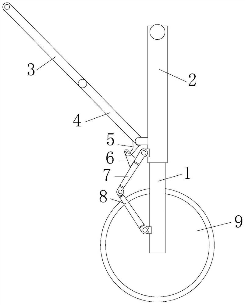
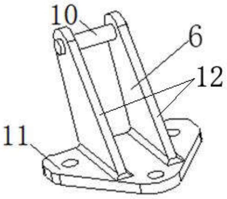
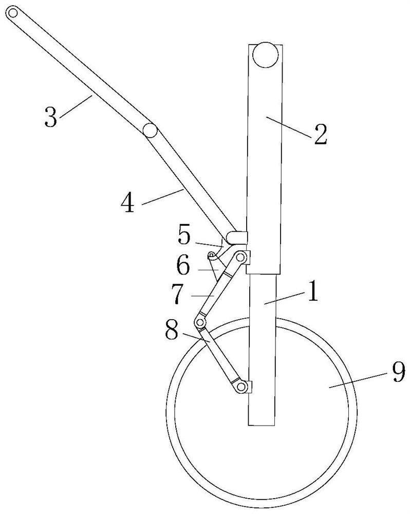
[0021] Such as Figure 1 to Figure 4 As shown, the present invention provides a leg-retracting mechanism of a pillar type landing gear, comprising a piston rod 1, an outer cylinder 2, an upper strut 3, a lower strut 4, a hook 5, a shackle 6, an upper torsion arm 7, a lower torsion arm Arm 8 and tire 9; One end of hook 5 is fixed on the lower strut 4, and the other end is located directly below one end of the shackle 6 and leaves a gap. The other end of the shackle 6 is fixed on the upper torque arm 7, and one end of the upper torsion arm 7 is connected to The outer wall of the outer cylinder 2 is rotationally connected, and the other end is rotationally connect...


PUM


Abstract

The invention discloses a pillar type landing gear leg retracting mechanism. The mechanism comprises a piston rod, an outer cylinder, an upper supporting rod, a lower supporting rod, a hook, a shackle, an upper torque arm, a lower torque arm and a tire; and one end of the hook is fixed on the lower supporting rod, the other end of the hook is located under one end of the shackle, a gap is reserved between the hook and the shackle, the other end of the shackle is fixed on the upper torque arm, two ends of the upper torque arm are respectively and rotatably connected with the outer wall of the outer cylinder and one end of the lower torque arm, the other end of the lower torque arm is rotatably connected with the outer wall of the piston rod, the two ends of the piston rod are respectively sleeved with the outer cylinder and connected to the tire, the two ends of the lower supporting rod are rotationally connected with the outer wall of the outer cylinder and one end of the upper supporting rod respectively, and the other ends of the outer cylinder and the upper supporting rod are rotationally connected with a machine body structure. When the landing gear is in a put-down state, the upper and lower supporting rods are unfolded and fixed, and the hook does not make contact with the shackle; and when the landing gear is in a folded state, the upper and lower supporting rods are folded, the hook hooks the shackle to drive the piston rod to contract relative to the outer cylinder, and the purpose of leg contraction of the landing gear is achieved. The mechanism has the advantages of being simple in structure and high in reliability.

Description

technical field [0001] The invention belongs to the field of structural design and application of landing gear, and in particular relates to a leg retracting mechanism of a pillar type landing gear. Background technique [0002] Aircraft landing gear system is one of the most important systems of the aircraft. When the aircraft is flying, in order to reduce drag and improve aerodynamic performance, most aircraft store the landing gear in the fuselage or wing. However, the space available for storage of the landing gear in the general airframe is very compact, and even the scheme fails due to insufficient storage space, so it is required that the space occupied by the landing gear should be as small as possible after the landing gear is retracted. [0003] In order to reduce the storage space of the landing gear, the legs are properly retracted after the landing gear is retracted in place through a mechanism or a hydraulic transmission method. For the strut type landing gear...

Claims


Application Information

Patent Timeline
Patent Type & Authority Applications(China)
IPC IPC(8): B64C25/20
CPCB64C25/20Y02T50/40
Inventor 黎永平王进剑夏佳丽李彬龙思海石飞沈文静徐世华
Owner JIANGXI HONGDU AVIATION IND GRP
Learn More