
Paint spraying device for round block hole type graphite heat exchanger

A graphite heat exchanger and hole-type technology, applied in the direction of spraying devices, etc., can solve the problems of easily damaged workpiece surface, cumbersome clamping operation, inconvenient use, etc., and achieve the effect of avoiding workpiece damage, saving manpower and material resources, and simple operation

Active Publication Date: 2022-02-11
江苏苏宇化工设备有限公司
View PDF5 Cites 1 Cited by
  • Summary
  • Abstract
  • Description
  • Claims
  • Application Information

AI Technical Summary

Problems solved by technology

[0004] Aiming at the deficiencies of the prior art, the present invention provides a paint spraying device for a round hole graphite heat exchanger, which solves the problem that the current round hole graphite heat exchanger usually needs a large clamping force to fix it during painting. However, the fixture structure is complex, the clamping operation is cumbersome, inconvenient to use, and the large clamping force is easy to damage the surface of the workpiece

Method used


Image

  • Paint spraying device for round block hole type graphite heat exchanger
  • Paint spraying device for round block hole type graphite heat exchanger
  • Paint spraying device for round block hole type graphite heat exchanger

Examples


Embodiment 1

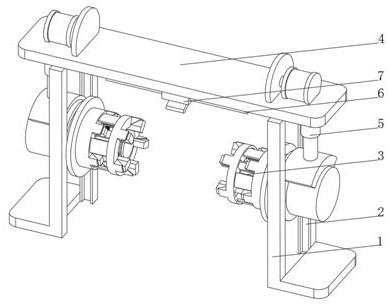
[0038] see Figure 1-3, the present invention provides a technical solution: a paint spraying device for a round hole graphite heat exchanger, specifically comprising:

[0039] The fixed bracket 1 is provided with a slideway 2 on both sides of the fixed bracket 1, and the inner wall of the slideway 2 is slidably connected with a positioning device 3, and one end of the positioning device 3 extends to the outside of the fixed bracket 1.

[0040] The fixed top plate 4, the bottom of both ends of the fixed top plate 4 are fixedly connected with the top of the fixed support 1, and the part of the fixed top plate 4 located at the inner side of the fixed support 1 is fixedly connected with a hydraulic lifting rod 5.

[0041] The fixed slideway 6 is arranged on the fixed top plate 4 and fixedly connected with the fixed top plate 4 , and the bottom of the fixed slideway 6 is slidably connected with a spraying device 7 .

[0042] Positioning device 3 includes:

[0043] The positionin...

Embodiment 2

[0051] see Figure 1-4 On the basis of Embodiment 1, the present invention provides a technical solution: the driving device 32 includes a hydraulic push rod 321, the outer side of the hydraulic push rod 321 is provided with an annular limit plate 322, and the top of one end of the hydraulic push rod 321 is fixedly connected with an arc Lifting plate 323, one end of the hydraulic push rod 321 away from the arc-shaped lifting plate 323 is fixedly connected with a rotating seat 324, and one side of the rotating seat 324 is fixedly connected with a driven gear 325, and a driving gear 326 is arranged above the driven gear 325, and the driving gear One side of 326 is fixedly connected with driving motor 327 through a rotating shaft, the top of arc-shaped lifting plate 323 is fixedly connected with the bottom of hydraulic lifting rod 5, the side of driven gear 325 away from rotating seat 324 is fixedly connected with positioning plate 31, and the ring-shaped limiting plate 322 Both ...

Embodiment 3

[0054] see Figure 1-5 , on the basis of Embodiment 1 and Embodiment 2, the present invention provides a technical solution: the spraying device 7 includes a sliding seat 71, the bottom of the sliding seat 71 is fixedly connected with the outer ring of the rotating bearing 72, and the inner ring of the rotating bearing 72 is fixedly connected There are arc-shaped spray nozzles 73, the top of the sliding seat 71 is connected to the fixed slideway 6 and slides on the fixed slideway 6, and the discharge nozzles at the bottom of the arc-shaped spray nozzle 73 are arranged in multiple groups and evenly distributed, and a spraying device 7 is provided. 7 The bottom is provided with an arc-shaped nozzle 73, which can adapt to the arc-shaped surface of the workpiece through the arc-shaped nozzle 73, avoiding the color difference caused by the different distances between the positions of the workpiece and the nozzle, and the arc-shaped nozzle 73 is on the sliding seat 71 through the rot...


PUM


Abstract

A paint spraying device for a round block hole type graphite heat exchanger, disclosed by the present invention, specifically comprises a fixing support, wherein sliding ways are formed in the two sides of the fixing support, positioning devices are slidably connected to the inner walls of the sliding ways, and one ends of the positioning devices extend to the outer side of the fixing support; a fixed top plate of which the bottoms at the two ends are fixedly connected with the top of the fixing support, wherein the parts, located on the inner side of the fixing support, of the two ends of the fixed top plate are fixedly connected with hydraulic lifting rods and fixed sliding ways, and the fixed sliding ways are arranged on the fixed top plate and fixedly connected with the fixed top plate. The present invention relates to the graphite heat exchanger paint spraying technical field, and according to the paint spraying device for the round block hole type graphite heat exchanger, positioning can be completed only by moving a positioning disc during positioning, the use and operation are easy, the clamping force can be freely and slowly increased or decreased, the situation that a workpiece is damaged due to the fact that the clamping force borne by the heat exchanger is too large is avoided, the workpiece does not need to be lifted to a clamping station for positioning and clamping, and the manpower and material resources are conveniently saved.

Description

technical field [0001] The invention relates to the technical field of painting for graphite heat exchangers, in particular to a painting device for round hole graphite heat exchangers. Background technique [0002] In the application of petroleum and chemical production, the heat exchanger is one of the most extensive unit equipment. It accounts for about 20% of the total investment in petroleum and chemical plant construction, and accounts for more than 40% of the chemical equipment in the whole plant. It is processed with graphite. There are many kinds of heat exchangers, such as round block hole type, tube and tube type, rectangular block hole type, plate type, squirrel cage type and so on. Considering the heat transfer efficiency, fluid flow resistance, structural strength, manufacturing cost, installation and maintenance of the heat exchanger, among them, the round hole graphite heat exchanger is the most widely used, and the round hole graphite heat exchanger, It is ...

Claims


Application Information

Patent Timeline
IPC IPC(8): B05B13/02B05B13/04
CPCB05B13/0285B05B13/0278B05B13/0235B05B13/0421
Inventor 夏汉林
Owner 江苏苏宇化工设备有限公司
Learn More