


Quick Research
Generate reliable direction feasibility study reports for your R&D in just a few steps.

Technical Q&A
Discover and master advanced knowledge NOW. Basics, ideas, possibilities, all at once.

Find Solutions
As an expert in R&D theories, this can generate solutions to your technical problems instantly.

Evaluate Feasibility
Analyze your overall solution with one click, know your potential R&D risks in advance.

Monitor Landscape
Get weekly tech updates, stay abreast of the latest tech innovations and key insights.
Passive wing telescopic structure
A telescopic structure and passive technology, applied in the direction of wing adjustment, fuselage, aircraft parts, etc., can solve the problems of high probability of being detected by reconnaissance, excessive wingspan of drones, and large space occupation, etc., to achieve production and maintenance Low cost, good telescopic stability, and simple mechanism
- Summary
- Abstract
- Description
- Claims
- Application Information
AI Technical Summary
Problems solved by technology
Method used
Image

Examples
specific Embodiment approach 1
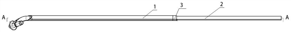
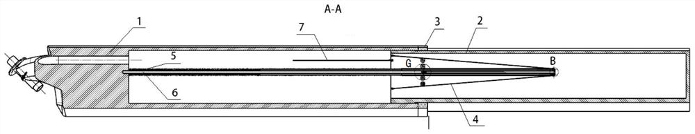
[0032] Specific implementation mode one: combine Figure 1 to Figure 11 Describe this embodiment, a passive wing telescopic structure described in this embodiment includes a wing 1, a telescopic wing 2, a linkage rope 7, a traction mechanism and a resettable telescopic mechanism, and the middle part of the front end of the wing 1 is provided with a slot. The end of the telescopic wing 2 is inserted into the slot, the telescopic wing 2 is connected to the wing 1 through a resettable telescopic mechanism, one end of the linkage rope 7 is fixedly connected to the end of the telescopic wing 2, and the other end of the linkage rope 7 passes through the slot Connect with the control mechanism that is positioned at fuselage behind the groove bottom, linkage rope 7 controls telescopic wing 2 telescopic by traction mechanism.
[0033] The interlocking rope 7 is used to lock the movement of the resettable telescopic mechanism and the traction mechanism, and the telescopic movement of th...
specific Embodiment approach 2
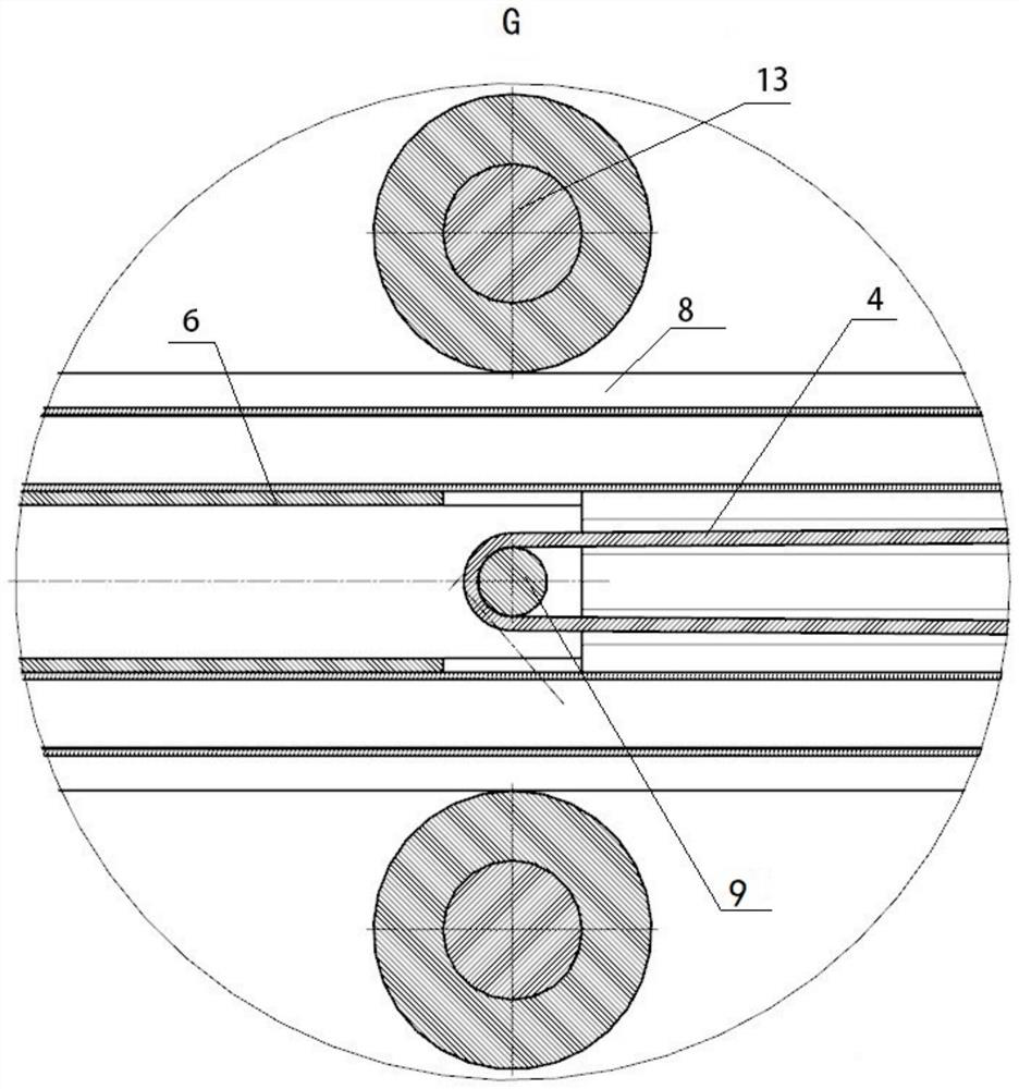
[0037] Specific implementation mode two: combination Figure 1 to Figure 11 Describe this embodiment, the resettable telescopic mechanism described in this embodiment includes an elastic member 5, a fixed rod 6 and a sliding rod 8, one end of the fixed rod 6 is fixedly connected to the groove bottom of the slot of the wing 1, and the other end of the fixed rod 6 Inserted in one end of the sliding rod 8, an elastic member 5 is provided between one end of the sliding rod 8 and the groove bottom of the slot, and the other end of the sliding rod 8 extends to the inside of the telescopic wing 2. Other compositions and connection methods are the same as those in Embodiment 1.
[0038] The resettable telescopic mechanism designed in this way utilizes the moving principle of the movable pulley, and the elastic member 5 is from Figure 6 The compressed state shown in stretches to figure 2 In the stretched state shown in , the stretched length is about half of the compressed length, ...
specific Embodiment approach 3
[0039] Specific implementation mode three: combination Figure 1 to Figure 11 Describe this embodiment, the elastic member 5 in this embodiment is a compression spring, and the compression spring is sleeved on the fixed rod 6 . Other compositions and connection methods are the same as those in the second embodiment.
PUM
 Abstract
Description
Claims
Application Information
 - R&D Engineer
- R&D Manager
- IP Professional
- Industry Leading Data Capabilities
- Powerful AI technology
- Patent DNA Extraction
Browse by: Latest US Patents, China's latest patents, Technical Efficacy Thesaurus, Application Domain, Technology Topic, Popular Technical Reports.
© 2024 PatSnap. All rights reserved.Legal|Privacy policy|Modern Slavery Act Transparency Statement|Sitemap|About US| Contact US: help@patsnap.com