


Quick Research
Generate reliable direction feasibility study reports for your R&D in just a few steps.

Technical Q&A
Discover and master advanced knowledge NOW. Basics, ideas, possibilities, all at once.

Find Solutions
As an expert in R&D theories, this can generate solutions to your technical problems instantly.

Evaluate Feasibility
Analyze your overall solution with one click, know your potential R&D risks in advance.

Monitor Landscape
Get weekly tech updates, stay abreast of the latest tech innovations and key insights.
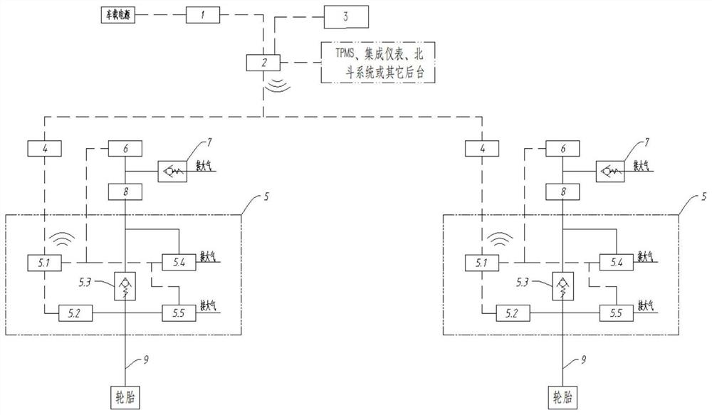
Tire inflation and deflation system and vehicle
A technology of inflating and deflating tires, applied in tire measurement, vehicle parts, tire parts and other directions, can solve the problems of operation safety impact, large maintenance cost, inability to work independently, and achieve low maintenance cost, good stability, The effect of convenient disassembly and assembly
- Summary
- Abstract
- Description
- Claims
- Application Information
AI Technical Summary
Problems solved by technology
Method used
Image

Examples
Embodiment Construction
[0045] Reference will now be made in detail to specific embodiments of the invention, examples of which are illustrated in the accompanying drawings. While the invention will be described in conjunction with specific embodiments, it will be understood that it is not intended to limit the invention to the described embodiments. On the contrary, it is intended to cover alterations, modifications and equivalents as included within the spirit and scope of the invention as defined by the appended claims. It should be noted that the method steps described here can all be realized by any functional block or functional arrangement, and any functional block or functional arrangement can be realized as a physical entity or a logical entity, or a combination of both.
[0046] In order to enable those skilled in the art to better understand the present invention, the present invention will be further described in detail below in conjunction with the accompanying drawings and specific embo...
PUM
 Abstract
Description
Claims
Application Information
 - R&D Engineer
- R&D Manager
- IP Professional
- Industry Leading Data Capabilities
- Powerful AI technology
- Patent DNA Extraction
Browse by: Latest US Patents, China's latest patents, Technical Efficacy Thesaurus, Application Domain, Technology Topic, Popular Technical Reports.
© 2024 PatSnap. All rights reserved.Legal|Privacy policy|Modern Slavery Act Transparency Statement|Sitemap|About US| Contact US: help@patsnap.com