
Power equipment control cabinet

A technology for controlling cabinets and power equipment, applied in the field of control cabinets, can solve problems such as poor protection performance, poor heat dissipation effect, and poor flexibility of use, and achieve the effects of easy maintenance, convenient operation, and extended service life

Pending Publication Date: 2022-01-28
天津市威匡电气设备有限公司
View PDF6 Cites 0 Cited by
  • Summary
  • Abstract
  • Description
  • Claims
  • Application Information

AI Technical Summary

Problems solved by technology

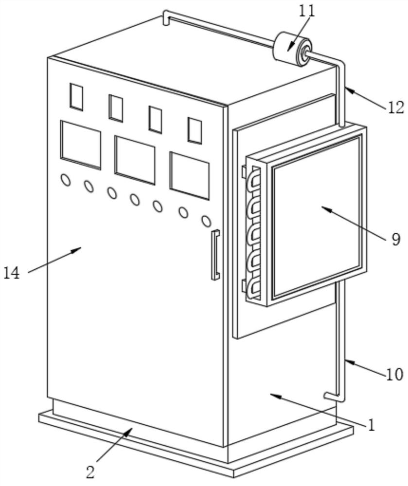
[0005] Aiming at the deficiencies of the prior art, the present invention provides a power equipment control cabinet, which solves the problem that it is difficult to adjust the number and height of the electrical component installation mechanism according to the actual use requirements, the use flexibility is poor, the heat dissipation effect is poor, and the protection performance is poor The problem

Method used


Image

  • Power equipment control cabinet
  • Power equipment control cabinet
  • Power equipment control cabinet

Examples


Embodiment Construction

[0031] The following will clearly and completely describe the technical solutions in the embodiments of the present invention with reference to the accompanying drawings in the embodiments of the present invention. Obviously, the described embodiments are only some, not all, embodiments of the present invention. Based on the embodiments of the present invention, all other embodiments obtained by persons of ordinary skill in the art without making creative efforts belong to the protection scope of the present invention.

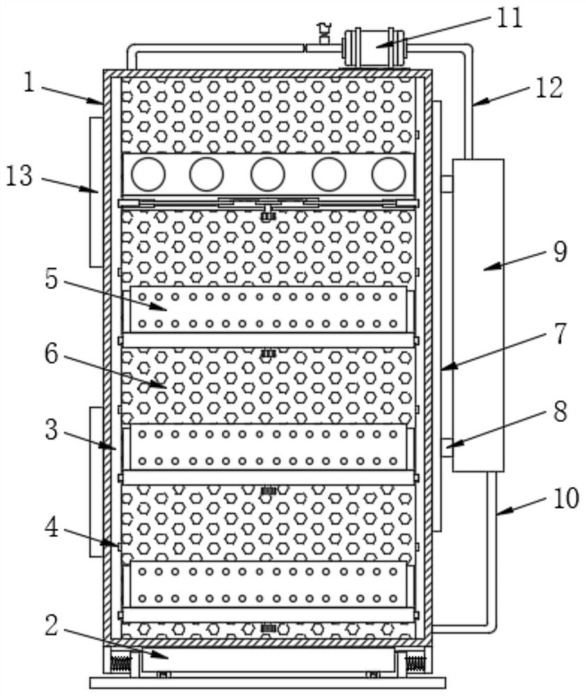
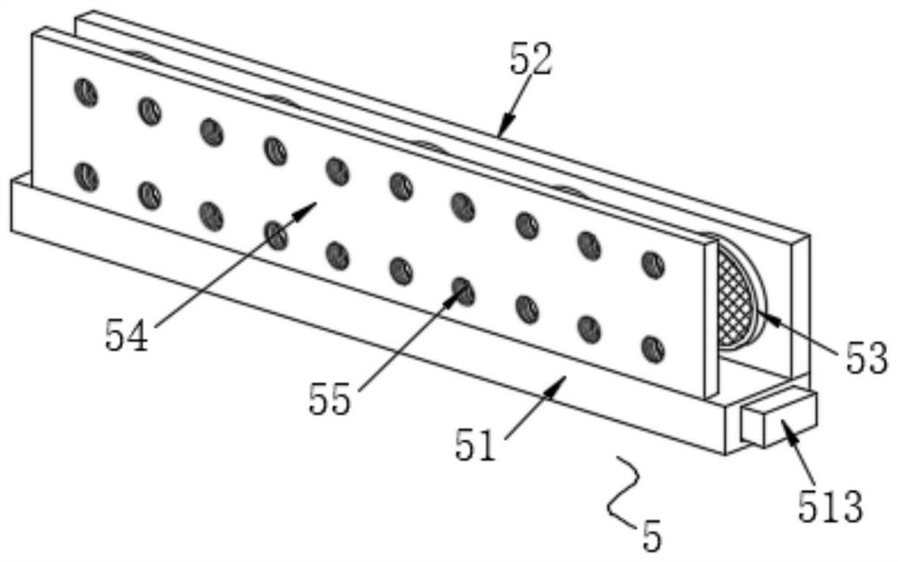
[0032] see Figure 1-7 , the embodiment of the present invention provides a technical solution: a power equipment control cabinet, including a cabinet body 1, a buffer mechanism 2 is provided at the bottom of the cabinet body 1, fixed plates 3 are fixedly connected to both sides of the inner wall of the cabinet body 1, and both sides The opposite sides of the two fixing plates 3 are provided with draw-in slots 4 , and a mounting mechanism 5 is arranged between...


PUM


Abstract

The invention discloses a power equipment control cabinet which comprises a cabinet body, a buffer mechanism is arranged at the bottom of the cabinet body, fixing plates are fixedly connected to the two sides of the inner wall of the cabinet body, clamping grooves are formed in the opposite sides of the two fixing plates, and a mounting mechanism is arranged between the opposite sides of the two fixing plates. The invention relates to the technical field of control cabinets. According to the electrical equipment control cabinet, clamping blocks can be retracted into limiting grooves by rotating knobs, the number and height of mounting mechanisms can be adjusted according to actual requirements, the electrical equipment control cabinet is high in use flexibility and convenient to operate, damaged electrical components can be maintained conveniently, practicability is improved, under the action of a conveying water pump, water flow circularly flows in a water inlet pipe, a condenser and a water outlet pipe, the heat dissipation effect of the control cabinet can be effectively improved in combination with a micro heat dissipation fan and a large heat dissipation fan, damage to electrical components caused by too high temperature is prevented, the service life of the control cabinet is prolonged, and the protection effect is good.

Description

technical field [0001] The invention relates to the technical field of control cabinets, in particular to a power equipment control cabinet. Background technique [0002] The control cabinet is to assemble the switchgear, measuring instrument, protective device and auxiliary equipment in the closed or semiclosed metal cabinet or on the screen width according to the requirements of electrical wiring. and the safety of surrounding equipment. During normal operation, the circuit can be connected or disconnected by means of a manual or automatic switch. Cut off the circuit or alarm with the help of protective electrical appliances in case of failure or abnormal operation. Various parameters in operation can be displayed by means of measuring instruments, and some electrical parameters can also be adjusted to prompt or send out signals for deviations from normal working conditions. Commonly used in various power generation, distribution and substations. [0003] The control c...

Claims


Application Information

Patent Timeline
Patent Type & Authority Applications(China)
IPC IPC(8): H02B1/54H02B1/56H02B1/30H02B1/32H02B1/38H02B1/36
CPCH02B1/54H02B1/565H02B1/30H02B1/32H02B1/38H02B1/36
Inventor 黄文荣南忠永
Owner 天津市威匡电气设备有限公司
Learn More