
Synthetic aperture radar coherent pulse signal generation method

A synthetic aperture radar and signal generation technology, applied in radio wave measurement systems, instruments, etc., can solve problems such as timing signal jitter, sampling clock deviation, non-ideal rectangular waves, etc., achieve good focusing, improve stability, and improve radar images. quality effect

Pending Publication Date: 2022-01-28
LEIHUA ELECTRONICS TECH RES INST AVIATION IND OF CHINA
View PDF0 Cites 1 Cited by
  • Summary
  • Abstract
  • Description
  • Claims
  • Application Information

AI Technical Summary

Problems solved by technology

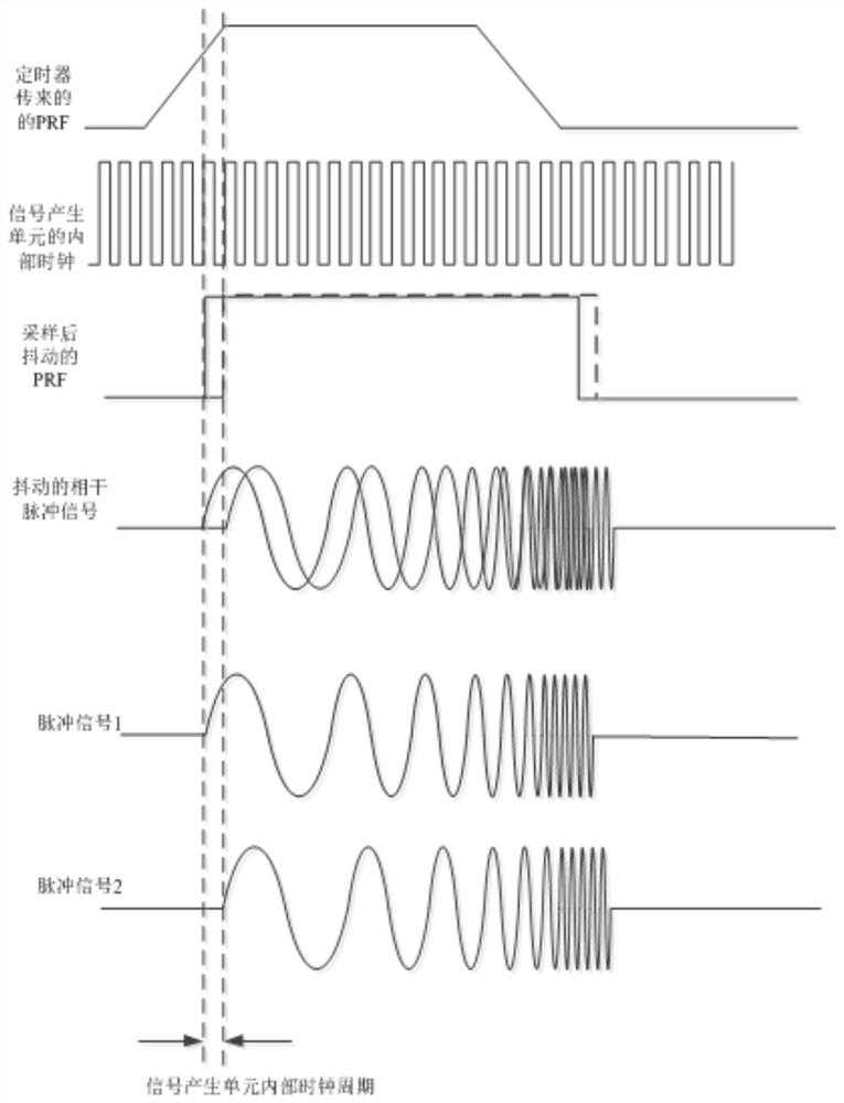
[0003] The traditional coherent pulse signal generation method has the following disadvantages: because the PRF signal generated by the timer is an unideal rectangular wave in practice, the rising edge of the rectangular wave has a certain width, and due to its own factors and external interference, the timing signal may have a certain The jitter, the signal generation unit sometimes has a sampling clock deviation when sampling and detecting it, which will cause a sampling time interval deviation between adjacent pulse signals generated, resulting in the radar sampling the echo signal When , there will be a certain deviation between adjacent pulses, the coherence between different pulse signals during a frame of image will become worse, and the radar image after imaging processing will appear ghosting and defocusing

Method used


Image

  • Synthetic aperture radar coherent pulse signal generation method
  • Synthetic aperture radar coherent pulse signal generation method

Examples


Embodiment Construction

[0017] In order to make the purpose, technical solution and advantages of the application more clear, the technical solution in the embodiment of the application will be described in more detail below in conjunction with the drawings in the embodiment of the application. In the drawings, the same or similar reference numerals denote the same or similar elements or elements having the same or similar functions throughout. The described embodiments are some, but not all, embodiments of the application. The embodiments described below by referring to the figures are exemplary, and are intended to explain the present application, and should not be construed as limiting the present application. Based on the embodiments in this application, all other embodiments obtained by persons of ordinary skill in the art without creative efforts fall within the protection scope of this application. Embodiments of the present application will be described in detail below in conjunction with th...


PUM


Abstract

The invention belongs to the field of radar system design, and particularly relates to a synthetic aperture radar coherent pulse signal generation method. The method comprises the following steps: step 1, waveform parameters of radar signals in an imaging mode are obtained, the waveform parameters of the radar signals are sent to a signal generation unit, and the signal generation unit receives and stores the waveform parameters of the radar signals; step 2, the signal generation unit detects the frame pulse signal of the timer in real time, and after the frame pulse signal is detected, the signal generation unit generates a PRF signal according to the waveform parameter of the radar signal and the frame pulse signal; and step 3, the signal generation unit generates a coherent pulse signal according to the waveform parameters of the PRF signal and the radar signal, sends the coherent pulse signal to the emission unit, amplifies the coherent pulse signal, and then radiates the coherent pulse signal through an antenna. The stability of the radar imaging function can be greatly improved, the image obtained after radar imaging is good in focusing and free of ghosting, and the radar image quality can be effectively improved.

Description

technical field [0001] The application belongs to the field of radar system design, in particular to a synthetic aperture radar coherent pulse signal generation method. Background technique [0002] Synthetic aperture radar is widely used in terrain surveying and mapping. When working, the radar continuously transmits multiple coherent pulse signals and receives echo signals. By synthesizing the echo signals, a well-focused terrain image is obtained. During the signal acquisition process of each frame of radar image, a high degree of coherence should be maintained between different pulse signals emitted by the radar, so that the radar can perform subsequent imaging processing. The coherence between pulse signals requires that different pulses have the same initial phase during a frame of image. The coherent pulse signal is generated by the signal generation unit based on the PRF signal of the timer. The timer and the signal generation unit in the synthetic aperture radar ar...

Claims


Application Information

Patent Timeline
IPC IPC(8): G01S7/28
CPCG01S7/28
Inventor 吴赛赛陈德民牛诚翔
Owner LEIHUA ELECTRONICS TECH RES INST AVIATION IND OF CHINA
Learn More