Device for adjusting tire posture and applying load

A technology of applying loads and tires, which is applied in the direction of automobile tire testing, etc., can solve the problems of complex structure and poor adjustment effect, and achieve the effect of precise action and comprehensive tire posture

Pending Publication Date: 2022-01-28
CITIC HEAVY INDUSTRIES CO LTD
View PDF0 Cites 0 Cited by
  • Summary
  • Abstract
  • Description
  • Claims
  • Application Information

AI Technical Summary

Problems solved by technology

[0003] The purpose of the present invention is to provide a device for tire posture adjustment and load application to solve the technical problems of existing tire posture adjustment devices with complex structure and poor adjustment effect in the prior art; many technologies provided by the present invention The many technical effects that the preferred technical solution in the scheme can produce (the mobile assembly includes two first telescopic mechanisms, a second telescopic mechanism, an upper support and a lower support, and the first telescopic mechanism, the upper support and the lower support are mutually Cooperate to form a link mechanism, which can realize the lifting and tilting of the tire, and the second telescopic mechanism can horizontally push the wheel frame connecting seat, which can realize the lateral displacement of the tire and the comprehensive adjustment of the tire posture; the moving component includes a sliding mechanism, which has the function of limiting and guiding. Effectively guarantee the accuracy and stability of tire lifting and rolling movements; the wheel frame connecting seat is provided with a slide rail, and the lower connecting part is provided with a sliding seat, and the two slidingly cooperate to ensure accurate horizontal displacement of the tire; the moving component includes a buffer mechanism, and the buffering effect Significantly; the slewing assembly includes a support mechanism, a slewing support and a ring motor. The support mechanism and the slewing support are mainly used for supporting and installing, and the ring motor is used to provide and transmit slewing power; the support mechanism includes an upper support seat assembly and a lower support seat assembly. The upper support The seat assembly and the lower support seat assembly are respectively provided with an accommodating cavity and a guiding cavity, which are respectively used for the installation, accommodation and guidance of the sliding mechanism; the load-bearing assembly includes a load-bearing component and a mounting component, and the load-bearing component is used as the load-bearing part of the entire device, and the load-bearing effect is remarkable , the installation component is used for the installation of the rotary assembly; the control system includes a main controller and a tire attitude sensing device, the main controller is used for device control, and the tire attitude sensing device can timely sense various parameters in the tire movement process and feed back to the controller , the tire posture adjustment is precise, the effect is remarkable, etc.); see the following for details

Method used


Image

  • Device for adjusting tire posture and applying load
  • Device for adjusting tire posture and applying load
  • Device for adjusting tire posture and applying load

Examples


Embodiment 1

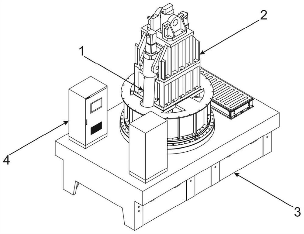
[0047] The present invention provides a device for tire posture adjustment and load application, such as figure 1 with figure 2 As shown, the device for tire posture adjustment and load application includes a moving assembly 1, a rotating assembly 2, a control system 4 and a bearing assembly 3, the moving assembly 1 is arranged on the rotating assembly 2, and the rotating assembly 2 is arranged on the bearing assembly 3 Above, the rotary assembly 2 and the mobile assembly 1 rotate synchronously to adjust the tire rotation angle; the bottom end of the mobile assembly 1 passes through the rotary assembly 2 and the bearing assembly 3, and is connected with the wheel frame connecting seat 5, which is used for the tire The installation of the mobile assembly 1 is used for tire lift, roll and lateral displacement; the mobile assembly 1 and the rotary assembly 2 are connected with the control system 4, and the control system 4 is used for the control of the rotary assembly 2 and the...

Embodiment 2

[0101] The difference between embodiment 2 and embodiment 1 is: as Figure 16-Figure 19 As shown, the number of buffer mechanisms 16 is set to two, which are symmetrically arranged on both sides of the upper support member 13 .

[0102] The upper support member 13 is arranged vertically, and its two sides are symmetrically provided with fourth mounting seats 132 , and the buffer end of the buffer mechanism 16 is hingedly arranged on the fourth mounting seats 132 .

[0103] The upper support seat assembly 211 is set as a second upper support 2114, the second upper support 2114 is set in a block shape, hollow structure, penetrates up and down, and forms an accommodating cavity 2113 inside, and the second upper support 2114 is detachably arranged on the support base 2121 , the upper support 13 is located above the second upper support 2114, and the second upper support 2114 is provided with a sixth mounting seat 21141 on the opposite side walls of both sides, the structure of the...


PUM


Abstract

The invention provides a device for adjusting tire posture and applying a load, relates to the technical field of tire detection devices, solves the technical problems that an existing tire posture adjusting device in the prior art is complex in structure and poor in adjusting effect, the device comprises a moving assembly, a rotating assembly, a control system and a bearing assembly. The moving assembly is arranged on the rotating assembly, and the rotating assembly is arranged on the bearing assembly and can drive the moving assembly to rotate; the bottom end of the moving assembly penetrates through the rotating assembly and the bearing assembly and is connected with a wheel carrier connecting base. The moving assembly is used for tire lifting, side tilting and transverse displacement. The moving assembly and the rotating assembly are both connected with the control system. Through mutual cooperation of the moving assembly, the rotating assembly, the bearing assembly and the control system, adjustment of the tire posture and application of load in the vertical direction can be achieved, the tire action is accurate, the effect is remarkable, meanwhile, the overall structure is simple and compact, and adjustment operation is convenient and fast.

Description

technical field [0001] The invention relates to the technical field of tire detection devices, in particular to a device for tire posture adjustment and load application. Background technique [0002] After the tire is manufactured, it is necessary to test the tire performance parameters on the tire test bench. At present, there are fixed and mobile test benches, and the tire adjustment and loading mechanism on the test bench is a key part. During the test, the tires need to be adjusted in different attitudes, such as tire roll and tire rotation, and different loads must be applied to the tires. Currently, multiple actuators are used in the existing structural design to realize tire The rotation of the tire is achieved through gear transmission, which not only has a complicated structure, but also has poor detection accuracy. At the same time, due to the lack of adjustment of the lateral movement of the tire during the moving test, an S-shaped track will appear, and the tire...

Claims


Application Information

Patent Timeline
Patent Type & Authority Applications(China)
IPC IPC(8): G01M17/02
CPCG01M17/02
Inventor 郝兵王守平陈士超冯小磊曾令琴张莉弯勇李振海曹正言张升奇杨武张将赵伟刚郭庶
Owner CITIC HEAVY INDUSTRIES CO LTD
Why Eureka
Try Eureka