Shield segment deformation monitoring system and monitoring method thereof

A shield segment and deformation monitoring technology, which is applied to measuring devices, instruments, optical devices, etc., can solve the problems of difficult installation and disassembly, incompatibility, and complex connection of cables, so as to reduce disassembly and installation steps, Improve monitoring efficiency and ensure the effect of battery life

Inactive Publication Date: 2022-01-28
THE 5TH ENG CO LTD OF CHINA RAILWAY 25TH BUREAU GRP +1
View PDF9 Cites 4 Cited by
  • Summary
  • Abstract
  • Description
  • Claims
  • Application Information

AI Technical Summary

Problems solved by technology

At present, the vertical and horizontal displacement monitoring of segments outside the shield frame section inside the tunnel is usually monitored by a level and a total station; for segments within the shield frame section, the internal space of the segment is basically covered by the shield tunnel. The frame is full, and there is only a gap of about 20 to 30 cm between the frame and the segments, so routine monitoring cannot be performed. The segments in this range can only be monitored after they come out of the shield frame, resulting in Displacement monitoring of segments within the frame section is still blank
However, in the early stage after the shield tunneling segment is installed, because the segment is affected by the earth pressure and synchronous grouting construction, it is the time period when the deformation of the segment structure is the largest. The absence of the segment has a huge adverse effect on the analysis of the structural shape and stress state of the segment during the construction and operation periods, so the monitoring of the segment displacement in the shield frame segment is very necessary and needs to be solved urgently
Existing automated displacement monitoring technologies have their own incompatibility due to space constraints or the dynamic advancement of the shield frame section
For example, a. The lamp target displacement monitoring system based on image recognition technology can automatically monitor horizontal and vertical displacements, but it is too large to be installed in a 30cm clearance space, and must be connected by cables, which is difficult to install and disassemble ; b. The static level monitoring system can carry out automatic monitoring of vertical displacement and is small in size, but due to the need to connect water pipes and air pipes, the installation is complicated and requires a large working surface, so it cannot be applied
The key point is that both of the above two schemes need to use cables for complex links, and installation and disassembly are not easy, so it is impossible to carry out dynamic forward monitoring with the advancement of the shield frame section. If the monitoring module is only installed and not disassembled, it is necessary to Monitoring the segments of the entire tunnel will be very expensive, making it impossible to apply

Method used


Image

  • Shield segment deformation monitoring system and monitoring method thereof
  • Shield segment deformation monitoring system and monitoring method thereof
  • Shield segment deformation monitoring system and monitoring method thereof

Examples


Embodiment 1

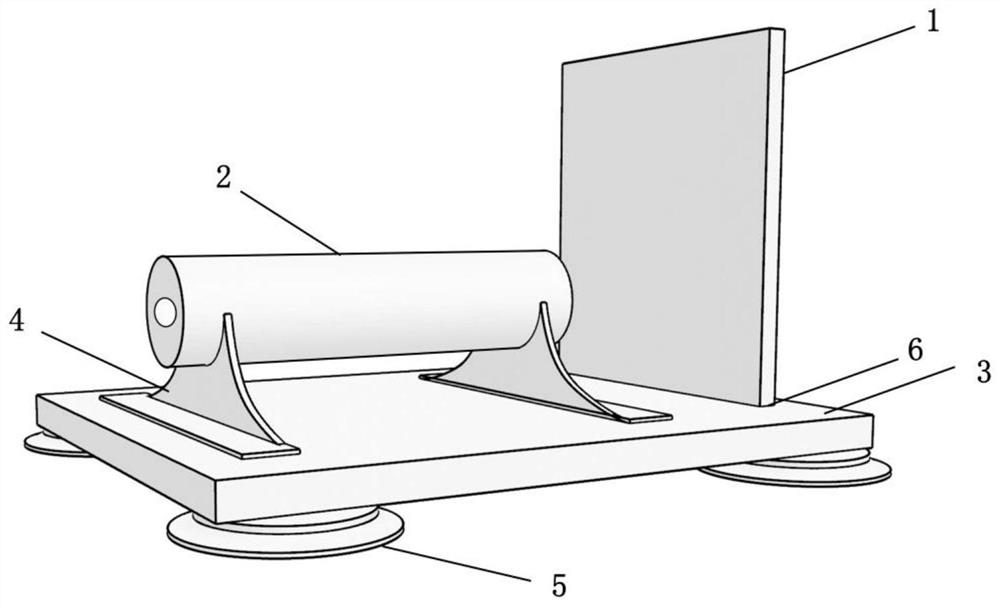
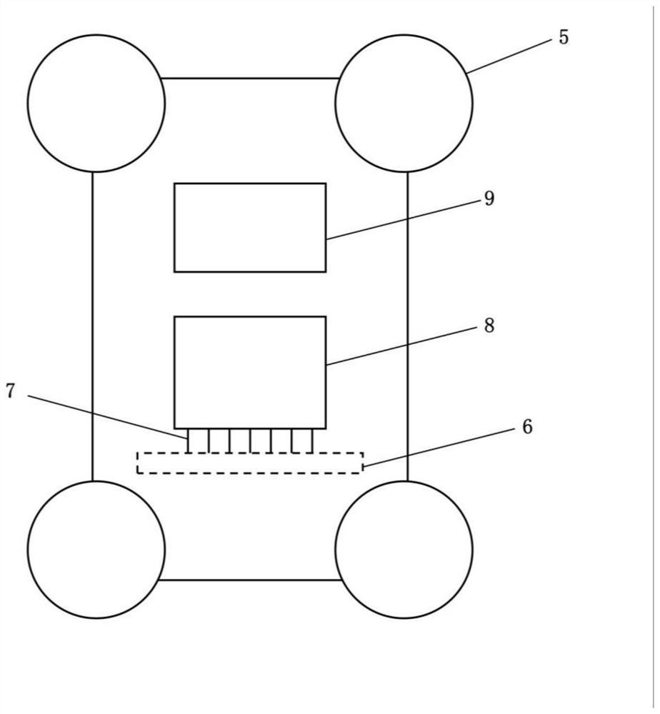
[0071] Example 1, such as Figure 1 to Figure 5 As shown, the shield segment deformation monitoring system described in this application includes multiple sets of laser sensing modules arranged along the shield segment propped up and constituting the frame section tunnel, as well as an automatic total station and a data processing platform;

[0072] Wherein, adjacent two groups of laser sensing modules are separated by at least one group of shield segments, and each group includes a CCD laser receiving target 1, a laser transmitter 2 and a data collector 3;

[0073] The CCD laser receiving target 1 is vertically fixed on the data collector 3 through the slot 6, and an attenuation sheet is installed on the CCD laser receiving target 1 to weaken the light intensity;

[0074] The laser transmitter 2 is fixed on the data collector 3 through the support 4;

[0075] Several vacuum chucks 5 are arranged at the bottom of the data collector 3 , and the laser sensing module is fixed on...


PUM


Abstract

According to the shield segment deformation monitoring system and the monitoring method thereof disclosed by the invention, a laser sensing technology is provided, and a cable-free link and independent lithium battery power supply mode is adopted, so that the purposes of convenient mounting and dismounting and controllable battery endurance time are achieved. By means of the monitoring system only covering the segments within the range of the shield frame section, low-cost monitoring can be achieved and the blank of the existing shield frame section segment deformation monitoring technology can be filled up through the monitoring means that the last measuring module is rapidly detached and installed to the foremost position in a mounting-dismounting-mounting dynamic circulation mode. The shield segment deformation monitoring system comprises a plurality of groups of laser sensing modules, an automatic total station and a data processing platform; two adjacent groups of laser sensing modules are spaced by at least one group of shield segments, and each group of laser sensing module comprises a CCD (Charge Coupled Device) laser receiving target, a laser transmitter and a data collector.

Description

technical field [0001] The invention relates to a system and a monitoring method for monitoring the deformation of a tunnel segment in a shield frame section by applying laser sensing technology, and belongs to the fields of rock and soil construction and tunnel engineering. Background technique [0002] With the rapid development of my country's economy, the construction of urban underground projects is limited by surface structures, and more and more shield tunneling methods are used in underground tunnel projects. After the construction of shield tunneling, segments need to be assembled for support to ensure that the tunnel section has standard firmness and stability. [0003] The vertical and horizontal displacement monitoring of tunnel segments is an important monitoring item during shield tunneling construction. At present, the vertical and horizontal displacement monitoring of segments outside the shield frame section inside the tunnel is usually monitored by a level...

Claims


Application Information

Patent Timeline
Patent Type & Authority Applications(China)
IPC IPC(8): G01B11/16
CPCG01B11/16
Inventor 鲍汝苍张旭海马国松李金明姜智彬刘国山岳晓东任大广郭明俊赵建军
Owner THE 5TH ENG CO LTD OF CHINA RAILWAY 25TH BUREAU GRP
Why Eureka
Try Eureka