Lifting hook device and lifting method

A hoisting method and hook technology, which is applied in the direction of transportation and packaging, load hanging components, etc., can solve the problems of low strength against accidental impact loads, hanging objects cannot be smoothly detached from the hook cavity, poor safety and reliability, etc., to achieve operational Convenience, simple structure, fast response effect

Pending Publication Date: 2022-01-28
河北巨力应急装备科技有限公司 +1
View PDF0 Cites 0 Cited by
  • Summary
  • Abstract
  • Description
  • Claims
  • Application Information

AI Technical Summary

Problems solved by technology

The safety device of the traditional hook is a combined structure of the torsion spring block. By installing the torsion spring, the block and the pin shaft at the body of the traditional hook, the block is pressed against the inner side of the hook head under the rebound force of the torsion spring to realize the prevention system. The risk of decoupling of hanging objects, but this structure has low strength against accidental impact loads, and the number of times of use is small. It is prone to deformation after repeated use. After deformation, the torsion spring will be damaged, and even the insurance card cannot be opened, and the hanging objects cannot be smoothly detached from the hook. Cavity
And the principle of this kind of safety structure is to hold the stopper against the inner side of the hook head, so the stopper occupies part of the space of the hook cavity, resulting in a reduction in the capacity of the hook cavity itself, so the safety and reliability of the traditional hook connection are poor

Method used


Image

  • Lifting hook device and lifting method
  • Lifting hook device and lifting method
  • Lifting hook device and lifting method

Examples


Embodiment 1

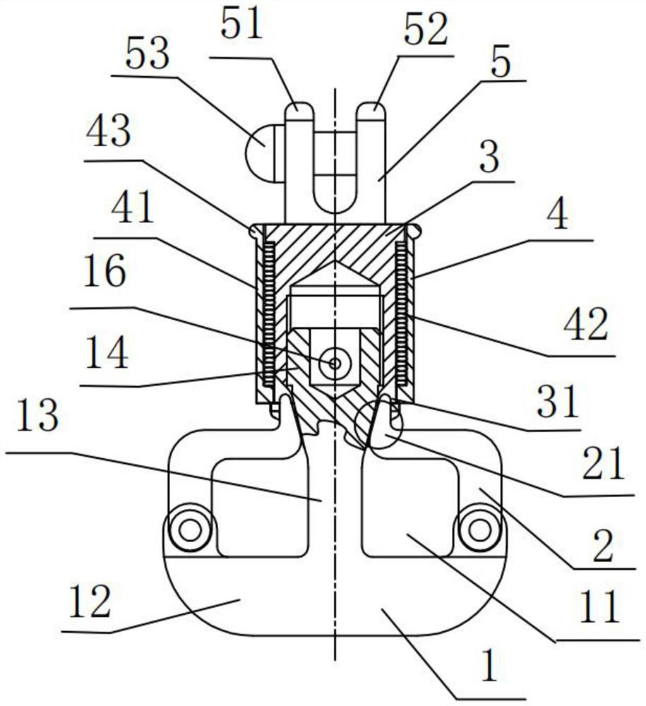
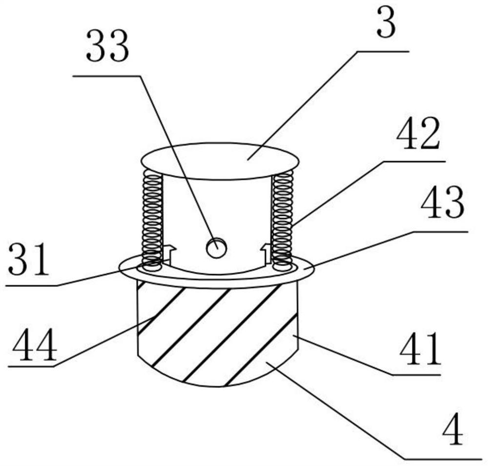
[0046] like figure 2 and image 3 As shown, the locking part 4 includes a locking sleeve 41 axially sleeved outside the connecting part, and a vertically arranged compression spring 42 located in the gap between the locking sleeve 41 and the connecting part 3. The height of the locking sleeve 41 is greater than or It is equal to the height of the connecting part 3, so that the compression spring 42 is completely covered in the gap. During installation, the bottom of the locking sleeve 41 can be against the upper surface of the top of the second connecting end 13, and the top of the locking sleeve 41 can extend upwards along the top of the connecting part 3; The inner extension of the bottom of 41 is against each other, and the top of the clip spring 42 is against the extension of the top of the connecting part 3. The bottom of the clip 41 is pressed downward by the clip spring 42 so that the clip 41 will move the free end of the movable knuckle 2. The hook point 21 is close...

Embodiment 2

[0065] like Figure 4 As shown, the locking part 4 in the first embodiment can also be a movable sleeve 45 with an internal thread on the inner wall, the height of the movable sleeve 45 is less than or equal to the height of the connecting part 3, and the outer wall of the connecting part 3 is equipped with External thread, during installation, the bottom of the movable sleeve 45 can abut against the upper end surface of the top of the second connecting end 13, and the top can abut against the extension edge of the top of the connecting part 3, and the movable sleeve 45 can pass along the connecting part. 3 is rotated up and down to open and close the limit groove 31, and the movable sleeve 45 seals the hook point 21 of the free end of the movable knuckle 2 in the limit groove 31, and by rotating the movable sleeve 45, the movable hook is realized. Tongue 2 has a limit fixing and release function. This locking method is more convenient for the operator to control the up and do...


PUM


Abstract

The invention discloses a lifting hook device and a lifting method, and relates to the field of hoisting. The lifting hook device comprises a hook body which is provided with at least one semi-closed hook cavity for hanging an object, and a first connecting end and a second connecting end which are positioned on two sides of the hook cavity; a movable hook knuckle one end of which is a positioning end and movably connected with the first connecting end, and the other end of which is a free end and used for opening and closing the coupler cavity; a connecting part the bottom of which is detachably connected with the second connecting end, wherein at least one limiting groove located in the moving path of the free end of the movable hook knuckle is formed in the connecting position, and the hook tip located at the free end of the movable hook knuckle can be completely contained in the limiting groove; a locking part which is axially arranged outside the connecting part in a sleeving manner and moves up and down along the connecting part to open and close the limiting groove; and a hanging part which is fixedly connected to the top of the connecting part and used for being connected with an external lifting appliance. According to the novel lifting hook device and the lifting method thereof, the structure is simpler, operation is convenient, safety is higher, deformation is not prone to occurring, and reliability is high.

Description

technical field [0001] The invention relates to the field of hoisting and hoisting, in particular to a hook device and a hoisting method. Background technique [0002] At present, there are many kinds of connection methods required for tethered reinforcement, so the requirements for the form of the connection device components are also increased. At present, the connection device is mainly a traditional single-hook structure, which can only realize single-point tethered connection at both ends. The safety device of the traditional hook is a combined structure of the torsion spring block. By installing the torsion spring, the block and the pin shaft at the body of the traditional hook, the block is pressed against the inner side of the hook head under the rebound force of the torsion spring to realize the prevention system. The risk of decoupling of hanging objects, but this structure has low strength against accidental impact loads, and the number of times of use is small. ...

Claims


Application Information

Patent Timeline
Patent Type & Authority Applications(China)
IPC IPC(8): B66C1/36
CPCB66C1/36
Inventor 杨超刘彦培张冠萍张立新赵丽杰李曜宗高海鹏赫铮
Owner 河北巨力应急装备科技有限公司
Why Eureka
Try Eureka