
Laminated plate forming device and forming method thereof

A forming device and a technology of laminated plates, which are applied to surface layering devices, ceramic molding machines, grinding drive devices, etc., can solve the problem of single arched beams, etc.

Active Publication Date: 2022-01-28
临泉晶宫绿建节能建筑有限公司
View PDF10 Cites 0 Cited by
  • Summary
  • Abstract
  • Description
  • Claims
  • Application Information

AI Technical Summary

Problems solved by technology

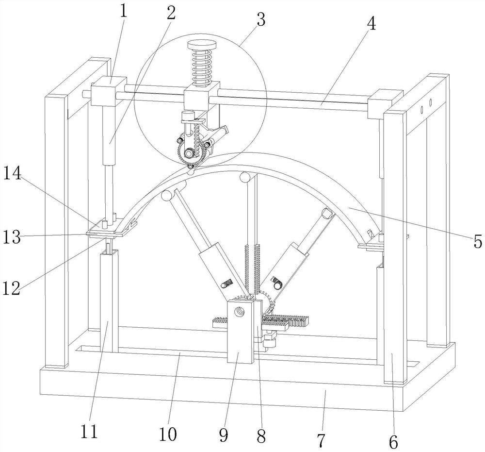
[0002]The laminated slab is an assembled integral floor slab composed of prefabricated beam slabs and cast-in-place reinforced concrete layers. The prefabricated beam slabs can be divided into straight beams according to the shape of the axis and curved beams, and curved beams are mainly arched beams, such as the composite beam prefabricated slab proposed by the application number 201811124869.1, the existing arched beams generally cooperate with each other through convex rollers and matching grooves, and the Straight beams are bent into arched beams. This method of producing arched beams has certain limitations. When the requirements for the curvature or radius of arched beams change, the existing production methods cannot be directly adjusted. The arched beam of the processed laminated slab is comparatively simple, for this reason, the present invention proposes a kind of laminated slab forming device and its forming method

Method used


Image

  • Laminated plate forming device and forming method thereof
  • Laminated plate forming device and forming method thereof
  • Laminated plate forming device and forming method thereof

Examples


Embodiment Construction

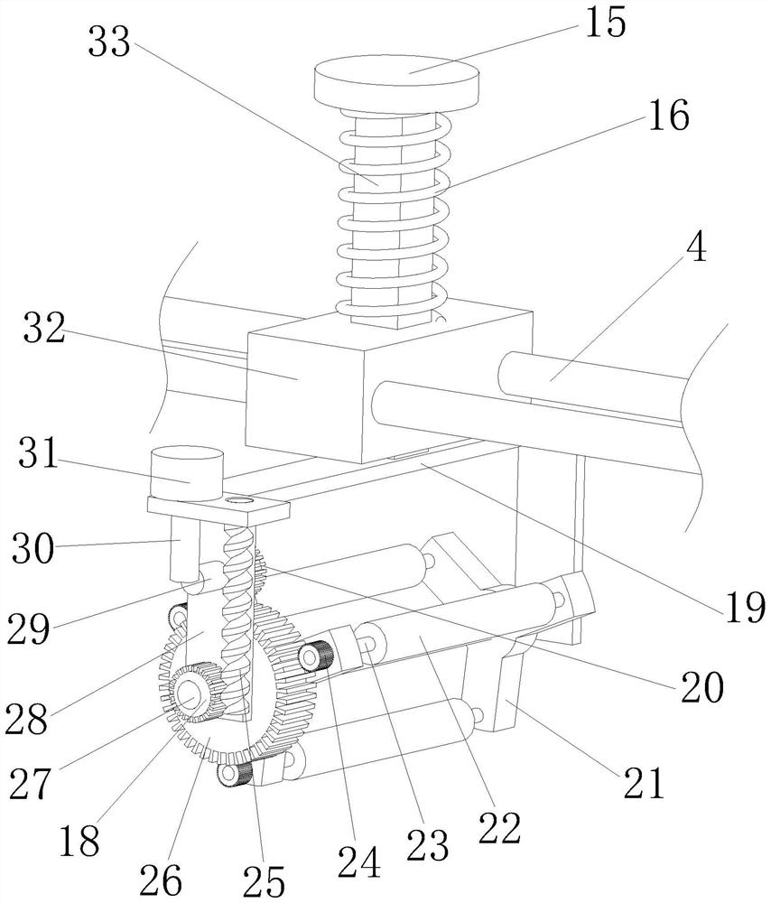
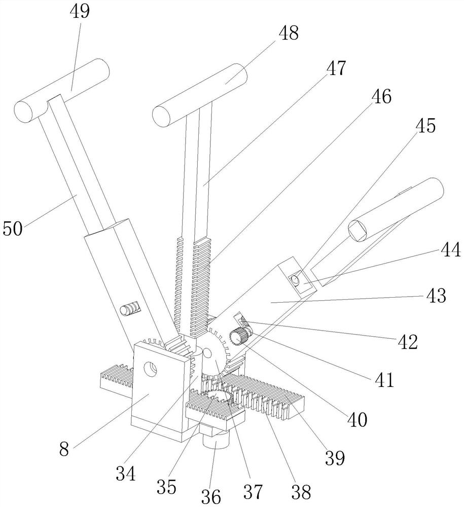
[0028] The following will clearly and completely describe the technical solutions in the embodiments of the present invention with reference to the accompanying drawings in the embodiments of the present invention. Obviously, the described embodiments are only some, not all, embodiments of the present invention.

[0029] refer to Figure 1-4 , a composite plate forming device and forming method thereof, comprising a base 7, two support plates 9 are fixedly connected to the base 7, a U-shaped plate 8 is fixedly connected between the two support plates 9, and the U-shaped plate The sides close to each other among the 8 are all rotatably connected with a sixth gear 37, and the bottom of the sixth gear 37 is meshed with a second rack 39, and the second rack 39 is slidingly connected with both sides of the U-shaped plate 8, and both sides Each of the second racks 39 close to each other is fixedly connected with a first rack 38, between the two first racks 38 is provided with a fift...


PUM


Abstract

The invention relates to the technical field of forming devices, in particular to a laminated plate forming device and a forming method thereof. The device in the following scheme comprises a base, two supporting plates are fixedly connected to the base, a U-shaped plate is fixedly connected between the two supporting plates, and sixth gears are rotationally connected to the sides, close to each other, of the U-shaped plate; second racks are engaged to the bottoms of the sixth gears, first racks are fixedly connected to the positions, close to each other, of the two second racks, a fifth gear rotationally connected with the bottom of the U-shaped plate is arranged between the two first racks, third rods are fixedly connected to the sixth gears, and first grooves are formed in the ends, away from the sixth gears, of the third rods; and fifth rods are slidably connected into the first grooves correspondingly, and one ends of the fifth rods extend out of the first grooves correspondingly and are rotationally connected with second rollers. The purpose that a straight beam can be bent into arched beams with different radians is achieved.

Description

technical field [0001] The invention relates to the field of forming devices, in particular to a laminate forming device and a forming method thereof. Background technique [0002] The laminated slab is an assembled integral floor slab formed by laminating prefabricated beams and slabs and cast-in-place reinforced concrete layers. Prefabricated beams and slabs can be divided into straight beams and curved beams according to the shape of the axis, and curved beams are mainly arched beams. No. 201811124869.1 proposed the composite beam prefabricated slab. The existing arched beams generally cooperate with the convex rollers and the matching grooves to bend the straight beams into arched beams. This kind of production of arched beams The method has certain limitations. When the requirements for the radian or radius of the arched beam change, the existing production method cannot be directly adjusted and changed. The arched beam of the laminated plate processed by it is relative...

Claims


Application Information

Patent Timeline
Patent Type & Authority Applications(China)
IPC IPC(8): B24B19/02B24B41/04B24B41/06B24B47/12B24B47/20B21D11/10B28B19/00
CPCB24B19/02B24B41/04B24B41/06B24B47/12B24B47/20B21D11/10B28B19/00
Inventor 倪合成
Owner 临泉晶宫绿建节能建筑有限公司
Learn More