Wet dust removal equipment for industrial waste gas dust

A technology for wet dust removal and industrial waste gas, which is applied in cleaning methods, use of liquid separation agents, construction, etc., can solve problems such as poor flexibility, inconvenient use, and low efficiency, and achieve good dust removal effects

Inactive Publication Date: 2022-01-28
魏然
View PDF0 Cites 2 Cited by
  • Summary
  • Abstract
  • Description
  • Claims
  • Application Information

AI Technical Summary

Problems solved by technology

[0004] In order to overcome the fixed dust removal area of ​​the traditional dust removal method, in larger factories, it is inconvenient to use and has poor flexibility. Most of them use artificial spraying mist for dust removal, but manual work alone is labor-intensive and inefficient. Dust removal The effect is poor and insufficient. The technical problem of the present invention is to provide a kind of wet dust removal equipment for industrial waste gas and dust that can be used flexibly.

Method used


Image

  • Wet dust removal equipment for industrial waste gas dust
  • Wet dust removal equipment for industrial waste gas dust
  • Wet dust removal equipment for industrial waste gas dust

Examples


Embodiment 1

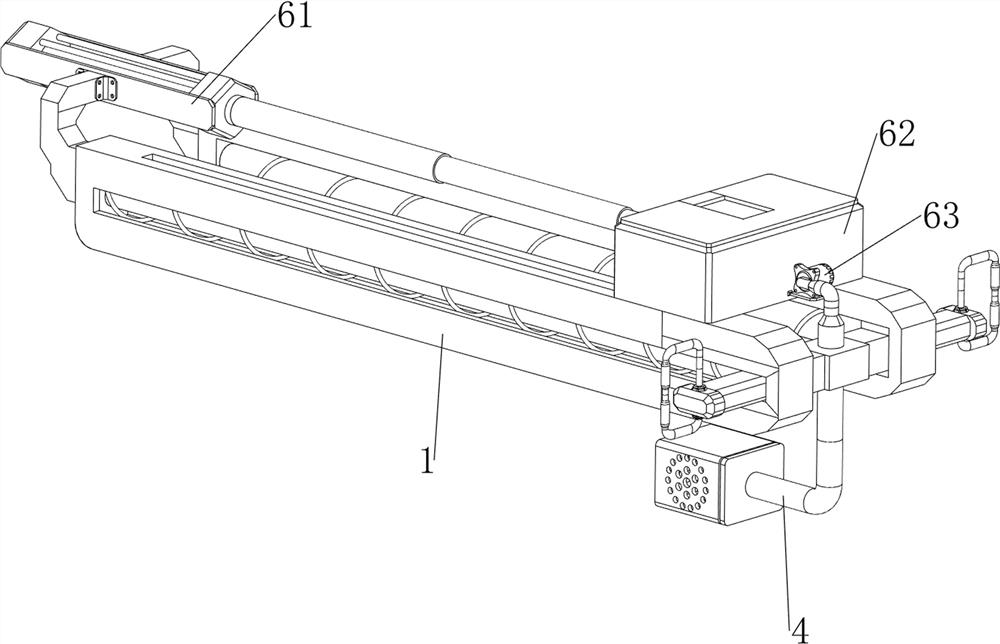
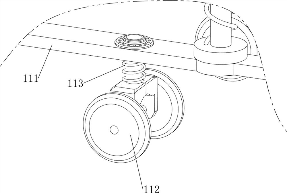
[0035] A wet dust removal equipment for industrial waste gas dust, such as figure 1 , figure 2 , image 3 , Figure 4 , Figure 11 and Figure 12 As shown, it includes a slide rail 1, a first slide bar 2, a first spring 3, a spray head 4, a moving handle 5, an automatic spraying mechanism 6, a lifting mechanism 9 and a moving mechanism 11, and the top of the moving mechanism 11 is provided with a lifting mechanism 9, The top of the lifting mechanism 9 is symmetrically provided with slide rails 1 front and back, and the slide rails 1 are provided with a first slide bar 2. There are two first slide bars 2, and a nozzle 4 is slidingly provided between the right sides of the first slide bar 2. The first spring 3 is connected between the front and rear sides of the nozzle 4 and the first slide bar 2. There are two first springs 3 in total. The upper part of the nozzle 4 is symmetrically provided with a moving handle 5, and the top of the slide rail 1 is provided with an automa...

Embodiment 2

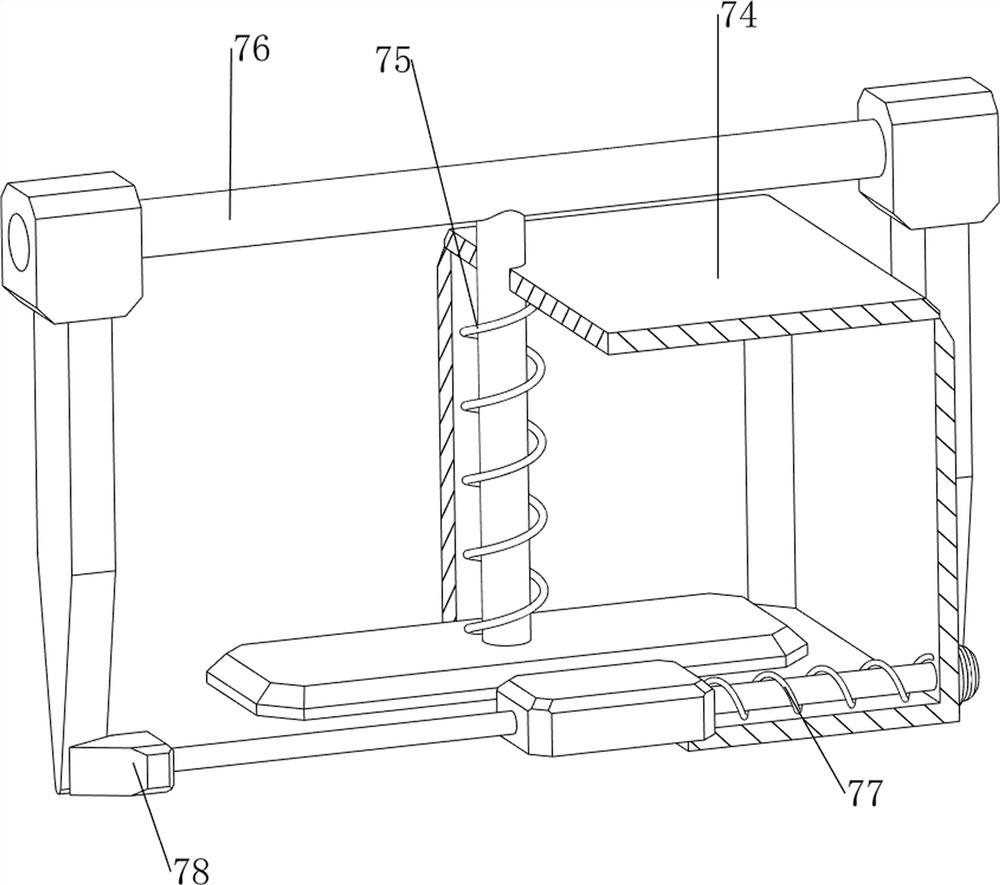
[0044] On the basis of Example 1, such as figure 1 , Figure 5 , Image 6 , Figure 7 , Figure 8 , Figure 9 , Figure 10 , Figure 13 , Figure 14 and Figure 15 As shown, a charging mechanism 7 is also included, and the charging mechanism 7 includes a first wedge-shaped rod 71, a second wedge-shaped rod 72, a first fixed rod 73, a casing 74, a second spring 75, a pull rod 76, and a third spring 77 And stop bar 78, the water tank 62 left side is provided with the second wedge-shaped bar 72 symmetrically front and back, the right side of water tank 62 front portion is provided with the first wedge-shaped bar 71, and the outer wall in the middle of slide rail 1 is provided with the first fixed bar 73, the first A housing 74 is provided between the fixed rods 73, a pull bar 76 is provided for sliding on the left side in the housing 74, a second spring 75 is connected between the bottom of the pull rod 76 and the inner top wall of the housing 74, and a stopper is provide...


PUM


Abstract

The invention relates to dust removal equipment, in particular to wet dust removal equipment for industrial waste gas dust. The wet dust removal equipment for the industrial waste gas dust is good in dust removal effect and can be flexibly used. The wet dust removal equipment for industrial waste gas dust comprises a moving mechanism, sliding rails, two first sliding rods, a spray head and two first springs; a height lifting mechanism for adjusting the wet dust removal equipment is arranged at the top of the moving mechanism; the sliding rails are symmetrically arranged at the top of the lifting mechanism; the first sliding rods are arranged on the sliding rails; the spray head used for spraying water mist is arranged between one sides of the first sliding rods in a sliding manner; and the first springs are connected between the two sides of the spray head and the first sliding rods. Clear water is poured into a water tank, a water pump is started to work, the water pump can pump the clear water to the spray head, water mist is sprayed from the spray head, dust removal can be conducted on the internal environment of a factory, manual spraying is not needed, and more labor is saved.

Description

technical field [0001] The invention relates to a dust removal device, in particular to a wet dust removal device for industrial waste gas dust. Background technique [0002] In some factories, a lot of dust will be generated in the internal environment, which not only has a great impact on the health of workers, but also pollutes the air. Generally, corresponding dust removal work will be done. The traditional dust removal method has a fixed dust removal area, and in larger factories. It is said that it is inconvenient to use and poor in flexibility. Most of them will use artificial spraying of water mist for dust removal, but manual work alone is labor-intensive, low in efficiency, poor in dust removal effect, and not sufficient. [0003] Therefore, it is necessary to design a wet dust removal equipment for industrial waste gas dust that has good dust removal effect and can be used flexibly. Contents of the invention [0004] In order to overcome the fixed dust removal ...

Claims


Application Information

Patent Timeline
Patent Type & Authority Applications(China)
IPC IPC(8): B01D47/06B05B15/68E01H3/02
CPCB01D47/06B05B15/68E01H3/02
Inventor 魏然
Owner 魏然
Why Eureka
Try Eureka