
Path track display method and device, electronic equipment and storage medium

A display method and path technology, applied in the field of electronic equipment, storage media, devices, and path path display methods, can solve the problems of inability to distinguish paths, confusion, and inability to accurately simulate complex paths, etc., and achieve the goal of visually displaying paths Effect

Pending Publication Date: 2022-01-25
RUN TECH CO LTD BEIJING
View PDF0 Cites 0 Cited by
  • Summary
  • Abstract
  • Description
  • Claims
  • Application Information

AI Technical Summary

Problems solved by technology

[0002] With the development of the information industry, people's lives have entered the era of big data. Conventional solutions for the analysis, processing, and calculation of massive information are no longer applicable, and algorithms are needed. bring convenience
With traditional visualization, complex trajectories cannot be accurately simulated, and there may be visual misreading at some intersections
For example, the simulation of a directed path such as bidirectional A address-B address-A address-C address, etc. When there are many elements, it will appear very confusing, the path cannot be distinguished, and there are typical problems such as node overlap and relationship crossing.
Based on the actual life scene, the present invention uses algorithms and JavaScript library to realize the purpose of direct application in daily life through simulated display, such as going through the maze and reaching the designated place, and solves the problem that the path cannot be distinguished when the path is displayed in the prior art. Typical problems such as node overlap and relationship intersection

Method used


Image

  • Path track display method and device, electronic equipment and storage medium
  • Path track display method and device, electronic equipment and storage medium
  • Path track display method and device, electronic equipment and storage medium

Examples


Embodiment 1

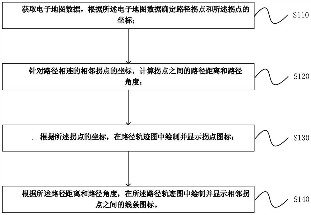
[0029] figure 1 It is a flow chart of a route track display method provided by Embodiment 1 of the present invention. This embodiment is applicable to the situation where the route is visually displayed. The method can be executed by a route track display device, which can be implemented by software and / or Or implemented by hardware, it can be configured in an electronic device with data processing capabilities, such as a server or a terminal device. The method specifically includes the following steps:

[0030] Step 110, acquiring electronic map data, determining the inflection point of the route and the coordinates of the inflection point according to the electronic map data;

[0031] Wherein, the electronic map data can be obtained based on, but not limited to, a Global Positioning System (GPS) signal; the inflection point of a path and the coordinates of the inflection point are determined according to the electronic map data; the inflection point of the path refers to th...

Embodiment 2

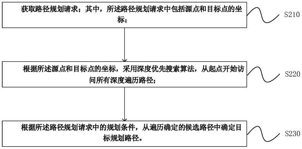
[0045] Figure 2a It is a flow chart of a route trajectory simulation display method provided by Embodiment 2 of the present invention. On the basis of the above-mentioned embodiments, this embodiment preferably also includes obtaining a route planning request; wherein, in the route planning request Including the coordinates of the source point and the target point; according to the coordinates of the source point and the target point, adopt the depth-first search algorithm to visit all the depth traversal paths from the starting point; according to the planning conditions in the path planning request, determine from the traversal Determine the target planning path among the candidate paths. The method of this embodiment includes:

[0046] S210. Obtain a path planning request; wherein, the path planning request includes coordinates of a source point and a target point;

[0047] In this embodiment, the route planning request may respond to the user's selection operation on th...

Embodiment 3

[0078] The route track display device provided in the embodiments of the present invention can execute the route track display method provided in any embodiment of the present invention, and has corresponding functional modules and beneficial effects for executing the method.

[0079] Such as image 3 As shown, the path trajectory display device includes: an inflection point acquisition module 31, a path calculation module 32, an inflection point display module 33 and a trajectory diagram display module 34;

[0080] An inflection point acquisition module 31, configured to acquire electronic map data, and determine a path inflection point and the coordinates of the inflection point according to the electronic map data;

[0081] The path calculation module 32 is used to calculate the path distance and path angle between the inflection points for the coordinates of the adjacent inflection points connected by the path;

[0082] An inflection point display module 33, co...


PUM


Abstract

The embodiment of the invention discloses a path track display method and device, electronic equipment and a storage medium. The method comprises the following steps: acquiring electronic map data, and determining a path inflection point and coordinates of the inflection point according to the electronic map data; calculating a path distance and a path angle between the inflection points according to the coordinates of the adjacent inflection points connected with the path; according to the coordinates of the inflection points, drawing and displaying an inflection point icon in a path track diagram; and drawing and displaying line icons between adjacent inflection points in the path track diagram according to the path distance and the path angle. By adopting the scheme, the path can be visually displayed when the path is displayed, and the purpose of being directly applied to life is achieved through analog display.

Description

technical field [0001] Embodiments of the present invention relate to the technical field of graphic visualization, and in particular, to a path trajectory display method, device, electronic equipment, and storage medium. Background technique [0002] With the development of the information industry, people's lives have entered the era of big data. Conventional solutions for the analysis, processing, and calculation of massive information are no longer applicable, and algorithms are needed. Bring convenience. With traditional visualization, complex trajectories cannot be accurately simulated, and there may be visual misinterpretations at some intersections. For example, the simulation of a directed path such as bidirectional A address-B address-A address-C address, etc. When there are many elements, it will appear very confusing, the path cannot be distinguished, and there are typical problems such as node overlap and relationship crossing. Based on the actual life scene, ...

Claims


Application Information

Patent Timeline
Patent Type & Authority Applications(China)
IPC IPC(8): G06Q10/04G06F16/29G06F16/54
CPCG06Q10/047G06F16/29G06F16/54
Inventor 尹长青万月亮火一莽
Owner RUN TECH CO LTD BEIJING
Learn More