
Anti-theft device for power cable

An anti-theft device and power cable technology, applied in the installation of cables, identification devices, signal devices, etc., can solve the problem of unable to prevent thieves from further stealing, dismantling anti-theft facilities, unable to stop theft and dismantling alarm devices, and daily patrol of operators. The problem of large inspection workload, etc., achieves the effect of comprehensive and reliable anti-theft structure, perfect anti-theft function, and comprehensive prevention of cable theft

Pending Publication Date: 2022-01-21
国网河南省电力公司尉氏县供电公司
View PDF18 Cites 0 Cited by
  • Summary
  • Abstract
  • Description
  • Claims
  • Application Information

AI Technical Summary

Problems solved by technology

[0004] (1) The anti-theft of traditional overhead cables relies on manual regular inspections. Since manual inspections are passive protection, it is generally difficult to detect theft during regular inspections; The daily inspection workload of personnel is increasing
[0005] (2) Some intelligent anti-theft devices are currently only equipped with monitoring cameras. The long-term use of monitoring cameras causes high pressure on data storage and transmission. Often when it is really necessary to retrieve on-site image capture evidence, the camera cannot reliably obtain evidence;
[0006] (3) The current camera monitors the anti-theft and cooperates with the buzzer or warning light to alarm. Its warning effect is limited, and it cannot prevent further theft and dismantling of anti-theft facilities by thieves.
For example, a power cable anti-theft alarm device disclosed in Chinese patent CN2015200996099 is detected by an infrared camera, an audible and visual alarm is used to alarm, and a data transmission monitoring center is included. However, this process is only a warning function and cannot stop the next thief from stealing and the act of dismantling the alarm

Method used


Image

  • Anti-theft device for power cable
  • Anti-theft device for power cable
  • Anti-theft device for power cable

Examples


specific Embodiment approach

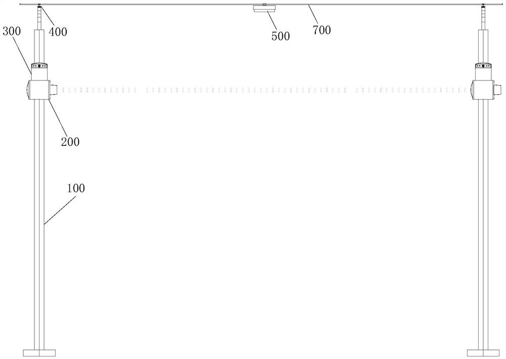
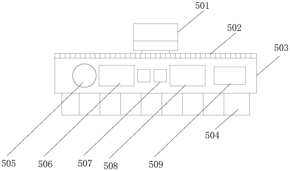
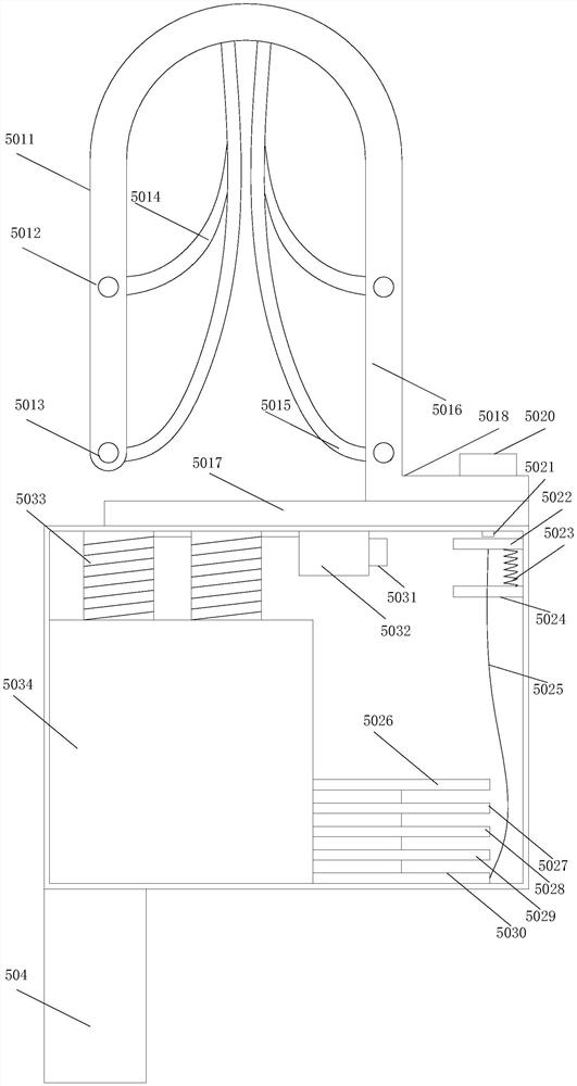
[0063] Such as Figure 1-13 As shown, it shows a specific embodiment of the present invention. As shown in the figure, a power cable anti-theft device disclosed in the present invention is used to monitor the cables 700 erected on a plurality of adjacent utility poles 100; Two adjacent utility poles 100 are equipped with a monitoring assembly for monitoring the thieves approaching the cable, and the middle position of the cable 700 on the two adjacent utility poles 100 is hung with an anti-theft sensor assembly 500, each utility pole The top of 100 is also provided with a pulling anti-theft component 400 for monitoring cable pulling;

[0064] The monitoring component includes a laser monitoring component 200 and a visual monitoring component 300;

[0065] The laser monitoring assembly 200 includes a lower box 201, one side of the lower box 201 is equipped with a laser receiving assembly 203 for receiving the laser signal of the laser monitoring assembly 200 on the previous ut...


PUM


Abstract

The invention discloses an anti-theft device for a power cable, which can timely and reliably discover abnormity along the cable erection direction, can perform evidence collection, warning and anti-disassembly and anti-theft on external damage, reduces the theft probability, and effectively protects the power cable. Two adjacent telegraph poles are respectively provided with a monitoring assembly used for monitoring that a thief gets close to the cable; an anti-theft sensing assembly is hung at the middle position of the cable on the two adjacent telegraph poles; the top end of each telegraph pole is further provided with a pulling anti-theft assembly used for monitoring cable pulling. The monitoring assembly comprises a laser monitoring assembly and a visual monitoring assembly; the laser monitoring assembly comprises a lower box body, and one side surface of the lower box body is provided with a laser receiving assembly used for receiving laser signals of the laser monitoring assembly on the previous telegraph pole. The other side face of the lower box body is provided with a laser emitting assembly used for emitting laser to the laser monitoring assembly of the rear telegraph pole in the cable erecting direction.

Description

technical field [0001] The invention relates to an anti-theft device for power cables, which is specifically used for anti-theft of cables of power transmission lines, especially for anti-theft of power transmission cables below 35kV. Background technique [0002] The high-density and long-length overhead cables of 35kV and below are widely used and are still the current mainstream cable laying method, accounting for a large proportion of urban power grids. For some people who steal cables, the common way of stealing is to cut the two ends of the cables and pull them to steal. With the increase of auxiliary tools, the theft of our transmission lines still exists (for example, for Chinese patents) A kind of cable anti-theft device disclosed by CN201010257195X, although the anti-theft capability increased by steel strands, the shearing capacity of the new hydraulic pliers can still easily cut the steel strands after the promotion), especially for those under the jurisdiction o...

Claims


Application Information

Patent Timeline
IPC IPC(8): G08B13/14H04N7/18G08B5/22G09F9/33H02G1/02H02G7/00
CPCG08B13/1409G08B13/1481H04N7/18G08B5/226H02G7/00H02G1/02G09F9/33
Inventor 卢强徐福强郭俊杰康建明杨卫礼周世华
Owner 国网河南省电力公司尉氏县供电公司
Learn More