Rotating shaft type variable-angle loading clamp based on light-gas gun and mounting method thereof
A technology of light gas gun and variable angle, which is applied in the field of high-speed impact test loading fixture and its installation, which can solve the problems of complex structure and difficulty in studying lightweight warheads at the same time, achieve high test efficiency, improve test success rate, and ensure accuracy The effect of positioning
- Summary
- Abstract
- Description
- Claims
- Application Information
AI Technical Summary
Problems solved by technology
Method used
Image
Examples
specific Embodiment approach 1
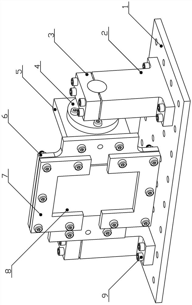
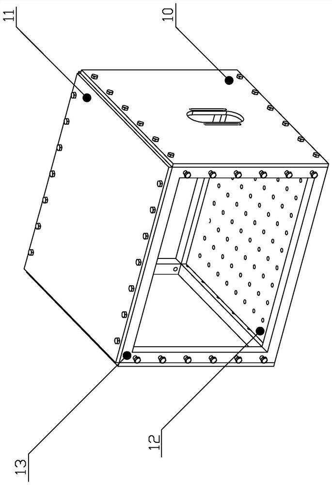
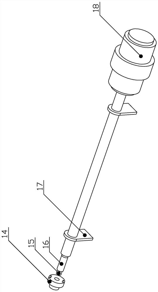
[0035] Specific implementation mode one: as Figure 1-Figure 5 As shown, this embodiment discloses a rotating shaft variable-angle loading fixture based on a light gas cannon, including a loading fixture, a protective device, and a hydrogen cannon assembly; the loading fixture includes a height-adjusting connecting plate 1, and two target plate supports 2. Two target plate fastening blocks 3, two adapter shafts 4, two connecting blocks 5, target plate rear clamp 6 and target plate front clamp 7; the protective device includes an incident plate 10, four protective plates 11, The target compartment is connected to the base 12 and the target compartment bearing frame 13; the light gas gun assembly includes a separation flange 14, a bullet holder 16, at least one light gas gun bracket 17 and a light gas gun 18;
[0036]The upper end face of the height-adjusting connecting plate 1 is arranged side by side with two target plate supports 2, and the two target plate supports 2 are det...
specific Embodiment approach 2
[0052] Specific implementation mode two: as figure 1 As shown, this embodiment is a further description of specific embodiment one. The semicircular groove provided on the lower end surface of the target plate fastening block 3 and the semicircular groove provided on the upper end surface of the target plate support 2 The shaped grooves are all knurled grooves; the outer wall surface of the shaft end of the adapter shaft 4 is provided with knurling. It is used to increase the frictional force and prevent the impact force from causing the adapter shaft 4 to rotate.
[0053] The two target plate supports 2 are used to support the target plate 8, the target plate front clamp 7, the target plate rear clamp 6, and the combination of the connecting block 5, and the two target plate supports 2 are arranged symmetrically on the left and right. The semicircular groove at the top is a knurling groove, and the effect of the knurling groove is to increase the frictional force, and is use...
specific Embodiment approach 3
[0056] Specific implementation mode three: as figure 1 , Figure 6 As shown, this embodiment is a further description of Embodiment 1. The center of the target plate rear clamp 6 is provided with a hollow 19, and the contour shape of the hollow 19 is triangle, square, polygon or circle.
[0057] The inner contour of the target plate rear fixture 6 is different according to the shape of the target plate 8 and the boundary condition requirements, and the above-mentioned different shapes are selected.
PUM
 Abstract
Description
Claims
Application Information
 - R&D
- Intellectual Property
- Life Sciences
- Materials
- Tech Scout
- Unparalleled Data Quality
- Higher Quality Content
- 60% Fewer Hallucinations
Browse by: Latest US Patents, China's latest patents, Technical Efficacy Thesaurus, Application Domain, Technology Topic, Popular Technical Reports.
© 2025 PatSnap. All rights reserved.Legal|Privacy policy|Modern Slavery Act Transparency Statement|Sitemap|About US| Contact US: help@patsnap.com


