Floor rubber pad thickness analysis method and system suitable for metro vehicles
An analysis method and rubber pad technology, which are applied in image analysis, use of optical devices, image data processing, etc., can solve the problem of low precision, and achieve the effect of ensuring accuracy, short time and convenient operation.
- Summary
- Abstract
- Description
- Claims
- Application Information
AI Technical Summary
Problems solved by technology
Method used
Image
Examples
Example Embodiment
[0045] Example 1
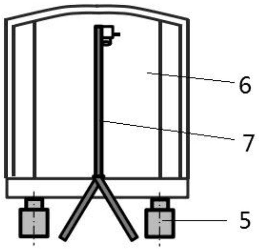
[0046] This example introduces an analytical system for a thickness analysis method of floor rubber mat, referencefigure 1 and figure 2 The system includes a controller and a detection mechanism; the detecting mechanism includes a stent and a measurement unit; the bracket includes a support 7 and a measuring arm 3, a slip drive mechanism is mounted on the measuring arm, and the measuring unit is slidably mounted on the measuring arm, sliding drive mechanism Drive connection measuring unit, the control end of the slip drive mechanism connects the controller.
[0047] The measuring unit includes a laser grid projector 1 and an image collector 2; the control terminal of the laser grid projector and the output of the image collector are respectively connected to the controller;
[0048] The controller controls the measurement unit by the slip drive mechanism to move on the measuring arm, and control the laser grid projector in the measuring unit to project grid line...
Example Embodiment
[0058] Example 2
[0059] This example describes a floor rubber mat thickness analysis method suitable for use in a subway vehicle, and can be implemented by the analysis system of Example 1, including:
[0060] Select the same height standard plane according to the reference plane of the vehicle floor to be tested;
[0061] Project the grid line to the standard plane, move the grid line image of all regions on the standard plane;
[0062] The initial bit data of each grid line intersection is calibrated according to the grid line image collected on the standard plane.
[0063] The grid line of the same parameter is projected to the surface of the vehicle floor surface, and the grid line image to be collected on the surface of the vehicle floor is collected;
[0064] The actual bit data of each mesh intersection is calculated based on the grid line image collected on the surface of the vehicle floor.
[0065] The height value of each mesh intersection is calculated based on the ac...
Example Embodiment
[0089] Example 3
[0090] Comprehensive Examples 1 and Example 2, the present invention relates to the application process of the thickness analysis of the vehicle floor with a thickness analysis.
[0091] S1, select the precision machining standard plane, and the hoist is up to the level 5. Place the support of the test mechanism at both ends of the standard plane, set up the measuring arm, mount the mounting of the measuring unit, and the measuring unit.
[0092] S2, turn on the semiconductor laser grid projection, project the grid line to the standard plane, measuring the longitudinal interval of the grid line with steel tape; start the CMOS camera to obtain the grid line image, determine the image data collected by the measurement data and the camera CMOS camera parameters and other related parameters, including CMOS camera lens focal length, amplification and laser mesh coordinates, etc.
[0093] S3, the initial position is calibrated: the control measuring unit moves from on...
PUM
| Property | Measurement | Unit |
|---|---|---|
| Wavelength | aaaaa | aaaaa |
Abstract
Description
Claims
Application Information
 - R&D
- Intellectual Property
- Life Sciences
- Materials
- Tech Scout
- Unparalleled Data Quality
- Higher Quality Content
- 60% Fewer Hallucinations
Browse by: Latest US Patents, China's latest patents, Technical Efficacy Thesaurus, Application Domain, Technology Topic, Popular Technical Reports.
© 2025 PatSnap. All rights reserved.Legal|Privacy policy|Modern Slavery Act Transparency Statement|Sitemap|About US| Contact US: help@patsnap.com


